 EN
EN

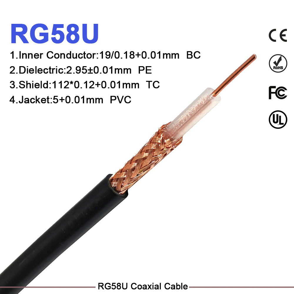
A 50 ohm coaxial cable operates as much more than a simple wire running between a transmitter and an antenna. It is a precision-engineered transmission line designed so that its physical geometry, dielectric material, center conductor, and outer shielding work together to transport high-frequency radio energy smoothly.
For RF system engineers, installers, and technical buyers, choosing the right line means matching the characteristic impedance of the transmission route to the radio equipment, mating connectors, and antenna arrays. Selecting cable based purely on outer thickness without evaluating impedance profile leads to preventable performance bottlenecks.
An impedance mismatch along the line creates reflected energy, distorts return loss measurements, and reduces overall link budget margins. Designing a reliable network requires evaluating signal frequency, physical run length, attenuation curves, power handling, mechanical flexibility, and environmental conditions.
What Determines the Impedance of a Coaxial Line?
Coaxial cable construction consists of four main layers: a center conductor, an insulating dielectric, an outer shielding braid or foil, and a protective outer jacket. The characteristic impedance of a 50 ohm coax line is determined primarily by the ratio between the outer diameter of the inner conductor and the inner diameter of the outer shield, alongside the dielectric constant of the insulating layer between them.
It is critical to remember that RF impedance cannot be measured using a basic DC resistance meter. The insulating material directly shapes electrical performance:
-
Solid Polyethylene: Provides robust mechanical protection and stable geometry for general-purpose applications.
-
Foam Polyethylene: Incorporates gas bubbles to reduce dielectric loading, lowering overall signal loss.
-
PTFE Insulators: Chosen for high-power, high-temperature, or extreme military and aerospace environments.
Conductor materials and surface plating also impact signal propagation as operational frequencies climb. Shielding layers like tinned copper braids or aluminum foil block external interference, but the overall cable assembly must maintain its circular geometry during installation. Deforming a 50 ohm coaxial cable by pinching or crushing it alters internal spacing, causing localized impedance shifts that degrade signal flow.
Why 50 Ohms Serves as the Universal RF Benchmark
The 50-ohm standard emerged as an ideal engineering compromise between maximum power handling capacity and minimum signal attenuation across air-spaced and solid dielectric coaxial designs.
Because of this balance, 50-ohm architecture became the primary specification across radio transmitters, cellular base stations, Wi-Fi infrastructure, test equipment, and antenna feed lines. Achieving maximum power transfer across these systems depends on end-to-end matching: the transmitter port, interconnect jumpers, primary feed line, connectors, and antenna must all share a true 50 ohm coax rating.
When equipment documentation specifies a 50-ohm signal path, introducing hardware with a different impedance rating creates signal reflections and standing waves. While small impedance variations may cause minimal disruption at low frequencies over short distances, they trigger significant insertion loss and measurement errors in high-frequency wireless networks.
Matching System Requirements: 50 Ohms versus 75 Ohms
While 50-ohm lines dominate two-way radio and wireless telecom, 75-ohm cable construction serves as the benchmark across television broadcasting, CATV distribution, and high-definition video lines.
Neither impedance standard is inherently superior; the correct choice depends entirely on system architecture:
-
Video and Broadcast Networks: Frequently utilize 75-ohm cable because it optimizes signal voltage attenuation over long distribution runs.
-
Telecommunications and Wireless: Depend on 50-ohm lines to optimize RF power handling between transmitters and antennas.
Substituting a 75-ohm cable like an rg11 coaxial cable into a 50-ohm radio feed line creates an impedance mismatch at both connection ends. While mechanical adapters allow an rg11 coaxial cable to physically interface with N-type or SMA equipment ports, an adapter cannot eliminate the underlying electrical mismatch. Always confirm equipment requirements before finalizing hardware procurement.
Evaluating Cable Size, Attenuation, and Shielding Performance
All coaxial lines attenuate RF energy, with loss increasing progressively as frequency and line length increase. Larger cable options feature thicker center conductors and expanded dielectrics, resulting in lower loss per meter. However, larger lines are heavier, stiffer, and require wider bend radii during installation.
Shielding coverage becomes essential when routing lines near power supplies, industrial motors, or adjacent transmitters. A double-shielded 50 ohm coaxial cable combining foil and braid layers prevents signal leakage and protects weak receive signals from external noise.
For short patch leads inside equipment cabinets, mechanical flexibility often takes priority over low attenuation. An rg58 50 ohm coax cable serves as a popular choice for short interconnects, bench testing, and mobile vehicle installations where tight routing is required.
Conversely, long outdoor runs to tower-mounted antennas require heavy-duty low-loss cable to keep signal attenuation within acceptable link budgets.
Protecting Internal Geometry During Installation
Preserving electrical performance requires careful handling during field deployment:
-
Observe Minimum Bend Radius: Avoid sharp bends that crush internal dielectric layers and displace the center conductor.
-
Avoid Physical Stress: Prevent cable twisting, heavy clamping, or excessive pull tension at connector rear barrels.
-
Incorporate Service Loops: Leave slack loops at equipment entry points to relieve mechanical strain and allow future maintenance.
-
Apply Weatherproofing Seals: Seal all exterior connector interfaces with cold-shrink tubing or self-amalgamating tape to block moisture ingress.
After completing installation, field crews should conduct continuity and return loss testing using sweep meters to confirm that bending or routing did not damage the line geometry.
Key Procurement Considerations for Project Engineering
When should an RG58 cable be specified?
An rg58 50 ohm coax cable is ideal for short jumpers, mobile radio harnesses, and indoor patch leads where flexibility is required and overall signal attenuation remains minimal over short distances.
Can a 75-ohm cable replace a 50-ohm line in a radio system?
No. Installing a 75-ohm line like an rg11 coaxial cable in a 50-ohm system introduces an impedance mismatch that causes signal reflection, elevated VSWR, and potential transmitter output stage heating.
Streamlining RF Systems with Precision Manufacturing
Building reliable wireless networks requires sourcing coaxial components and custom assemblies from manufacturing partners who enforce strict dimensional tolerances, precise impedance matching, and reliable global supply chains. Inconsistent dielectric dimensions or poor ferrule crimping degrade return loss and inflate path loss across communications networks.
Worldpeak delivers precision-engineered 50 ohm coaxial cable spools, flexible rg58 50 ohm coax cable jumpers, low-loss feeder assemblies, and custom connector hardware for commercial, industrial, and broadcast applications globally. Supported by automated stripping and crimping machinery, rigorous VSWR testing, and complete batch traceability, Worldpeak provides dependable interconnect solutions designed for demanding deployments.
Whether your next build requires bulk 50 ohm coax lines, flexible jumper assemblies, or specialized outdoor feed hardware, partnering with Worldpeak keeps network infrastructure projects moving forward on schedule.
Frequently Asked Questions
What is the main difference between 50-ohm and 75-ohm coaxial lines?
A 50 ohm coaxial cable is designed to optimize RF power handling in wireless, cellular, and two-way radio systems. A 75-ohm cable optimizes signal voltage transmission for video, CATV, and digital TV broadcasts.
How does dielectric selection affect coaxial cable loss?
Foamed or air-spaced dielectrics contain air bubbles that lower the overall dielectric constant, resulting in lower signal attenuation per meter compared to solid polyethylene dielectrics.
Why is an RG58 cable unsuitable for long high-frequency runs?
An rg58 50 ohm coax cable features a relatively small center conductor and solid dielectric, which leads to higher attenuation per meter at frequencies above 400 MHz compared to larger low-loss cable options.





