 EN
EN

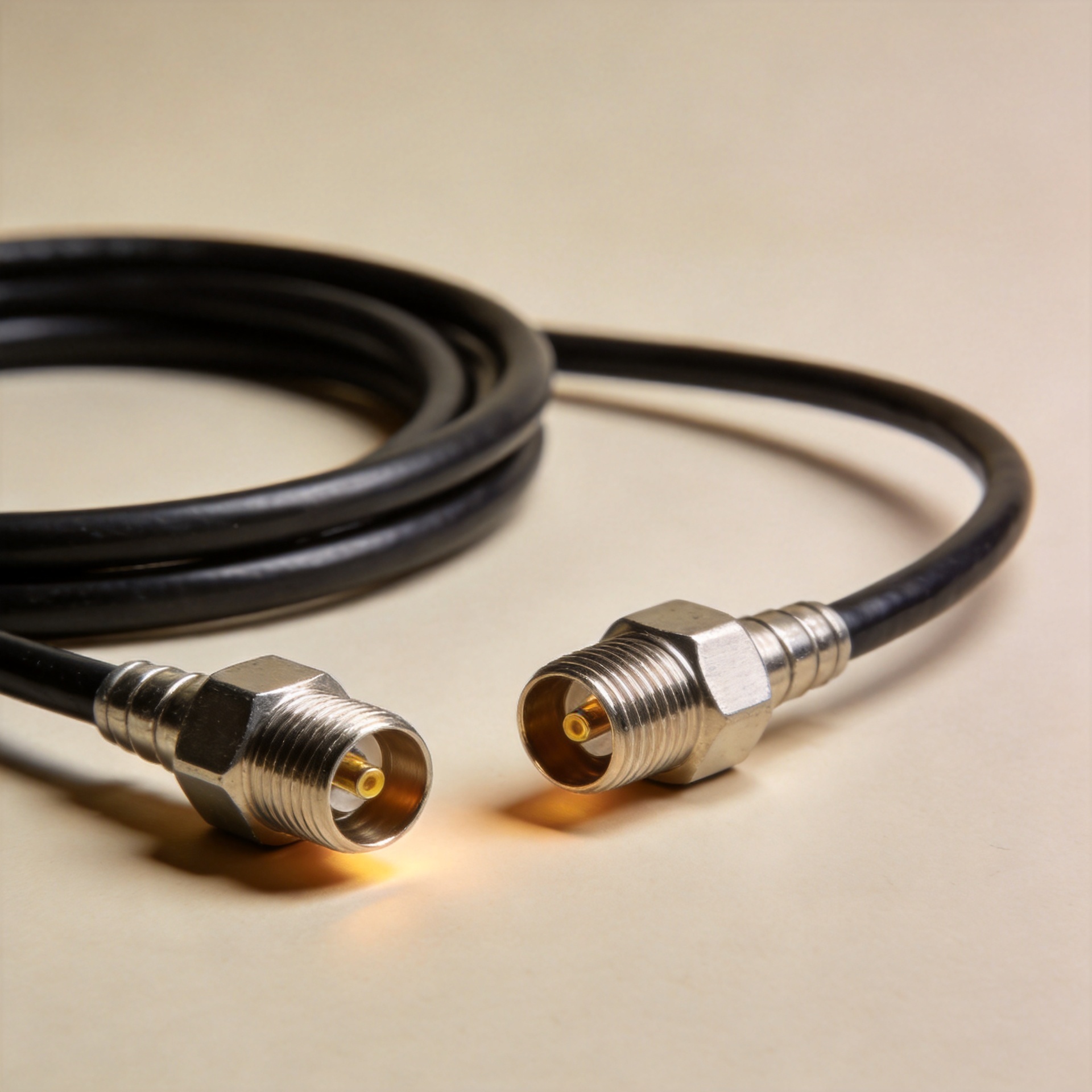
50 Ohm RF Cable: Standards, Types and Applications
A 50-ohm cable decision is rarely just a question of “will it connect?” In RF systems, the cable is part of the transmission path: its impedance, loss, shielding, bend behavior, and termination quality all affect the usable margin at the load. Having sourced RF components for infrastructure projects, I have learned that repeatable electrical performance and traceability across batches matter as much as the unit price. This article explains how to evaluate an rf cable 50 ohm specification for an engineering build or B2B purchase.
Why 50 Ohms Matters in an RF Cable Assembly
Characteristic impedance is the relationship the line presents to an RF signal as it travels along the cable. A source, transmission line, and load that are designed around 50 ohms can be matched to reduce reflections. The practical point is not that every 50-ohm assembly performs identically. Two cables can share a nominal 50-ohm impedance while using different conductor sizes, dielectric materials, shielding structures, and diameters. Those construction choices drive the compromises a buyer sees in loss, flexibility, power handling, and installation durability.
Start by treating impedance as a system requirement. If the equipment and connector interfaces call for 50 ohms, the cable, connectors, adapters, and assembly process all need to preserve that target. A cable with the right label but poor termination control can still introduce a discontinuity. The insertion-loss number on a datasheet is useful—actually, it is only the beginning—because final loss also depends on frequency, length, connector count, and routing.
The Three Specifications That Set the Selection Direction
1. Insertion loss at the operating frequency
Loss rises with frequency and cable length, so compare published attenuation at the actual operating band rather than relying on a low-frequency figure. A low loss coaxial cable 50 ohm construction is usually most valuable when the run is long, the receive signal is weak, or the link budget has little margin. For a short laboratory jumper, a more flexible cable may be the better trade even if its attenuation is not the lowest available. Ask for a loss table by frequency, the intended length, and the finished assembly configuration.
2. Shielding and the installation environment
Shielding limits unwanted coupling into and out of the cable. The right level depends on nearby transmitters, control cabinets, antenna routing, grounding practice, and the required measurement repeatability. In a static bench setup, routing convenience may dominate. In an outdoor feeder route or industrial enclosure, jacket resistance, moisture exposure, vibration, and the grounding approach deserve equal attention. Ask yourself: will the cable be fixed once, flexed during service, or exposed to repeated movement? That answer changes the construction choice.
3. Mechanical form factor and bend radius
Mechanical fit is not a packaging detail. A cable that must turn sharply in a constrained enclosure can be damaged or detuned if its minimum bend requirement is ignored. Conversely, a highly flexible construction may not offer the same routing stability as a more rigid option. Confirm cable diameter, bend guidance, connector orientation, strain relief, and the route before approving an RFQ.
Flexible, Semi-Rigid, and Corrugated 50-Ohm Cable Compared
| Type | Where it fits | Key advantage | Selection caution |
|---|---|---|---|
| Flexible coax | Test leads, equipment jumpers, serviceable assemblies | Easy routing and replacement | Check loss, shielding, and flex-life requirements rather than assuming all flexible cable is interchangeable. |
| Semi-rigid coax | Compact RF modules and controlled internal routing | Stable formed route and consistent geometry | Requires planned forming and careful handling; it is not suited to frequent repositioning. |
| Corrugated or hard-line feeder | Longer fixed infrastructure runs | Robust construction for installed routes | Verify routing space, connectorization, environmental sealing, and installation tooling. |
There is no universally suitable rf cable 50 ohm. If rapid installation and recurring service access are the primary constraints, flexible coax is often the practical choice. If geometry stability inside an RF enclosure is more important, semi-rigid cable deserves consideration. If the application is a fixed feeder route, a corrugated construction may align better with the mechanical environment. The decision should follow the signal path and service plan, not a generic preference.
Common 50-Ohm Cable Options in B2B Builds
For compact assemblies, coaxial cable rg58 50 ohm is a familiar category name, but buyers should still confirm the actual construction, frequency use case, jacket, and connector configuration with the supplier. A 50-ohm BNC cable can be appropriate where the equipment interface and application call for BNC mating; a 50 ohm bnc cable should not be substituted for another interface simply because the impedance matches.
Worldpeak’s confirmed product range illustrates why construction must match the job. The Worldpeak RG196 50-Ohm Coaxial Cable: Engineering Data & Selection Guide is relevant when reviewing compact 50-ohm coax options. For guarded measurement-oriented routing, review the TRC-50-2 Triaxial Cable - 50 ohm Guarded Coax. For an installed feeder context, the 1/2" Superflex Corrugated Copper Feeder Cable - 50 Ohm provides a relevant product reference. Confirm final electrical and mechanical specifications directly during quotation; titles alone are not a substitute for a project-specific datasheet review.
What to Include in an OEM RF Cable Request
OEM cable work becomes more reliable when the request is specific. Provide the impedance target, operating frequency range, assembly length and tolerance, connector series and gender, cable construction preference, routing constraints, shielding expectation, environmental conditions, labeling, test requirements, and forecast quantity. Also state whether the assembly is a prototype, a replacement part, or a recurring production item. This information lets a supplier assess whether the selected rf cable 50 ohm construction and termination process fit the application.
For volume purchasing, ask how electrical checks, connector torque control, visual inspection, and lot identification are handled. These are not promises of a particular test result; they are procurement questions that help compare supplier processes before a cable enters a critical signal chain.
50-Ohm RF Cable Selection Checklist
- Confirm that the source, cable, connectors, and load are all intended for 50 ohms.
- Set the highest operating frequency and evaluate loss at that frequency and required length.
- Define the routing: fixed feeder, cabinet route, internal module, bench jumper, or moving equipment.
- Choose flexible, semi-rigid, or corrugated construction based on bend, service, and stability needs.
- Specify connector interfaces and confirm that a 50-ohm BNC cable or other connector family matches the equipment—not just the impedance.
- Document shielding, jacket, environmental, labeling, and inspection requirements in the RFQ.
- Request project-specific drawings and datasheets before approving an OEM or production order.
Choose the Cable as Part of the Whole RF Path
The right rf cable 50 ohm is the one that maintains impedance continuity while fitting the frequency, loss budget, shielding environment, and installation geometry. A quick comparison of flexible, semi-rigid, and feeder constructions narrows the field, but the final answer comes from the application details. Begin with the full signal path, then use a clear RFQ to turn those requirements into an assembly a supplier can build and verify consistently.





