 EN
EN

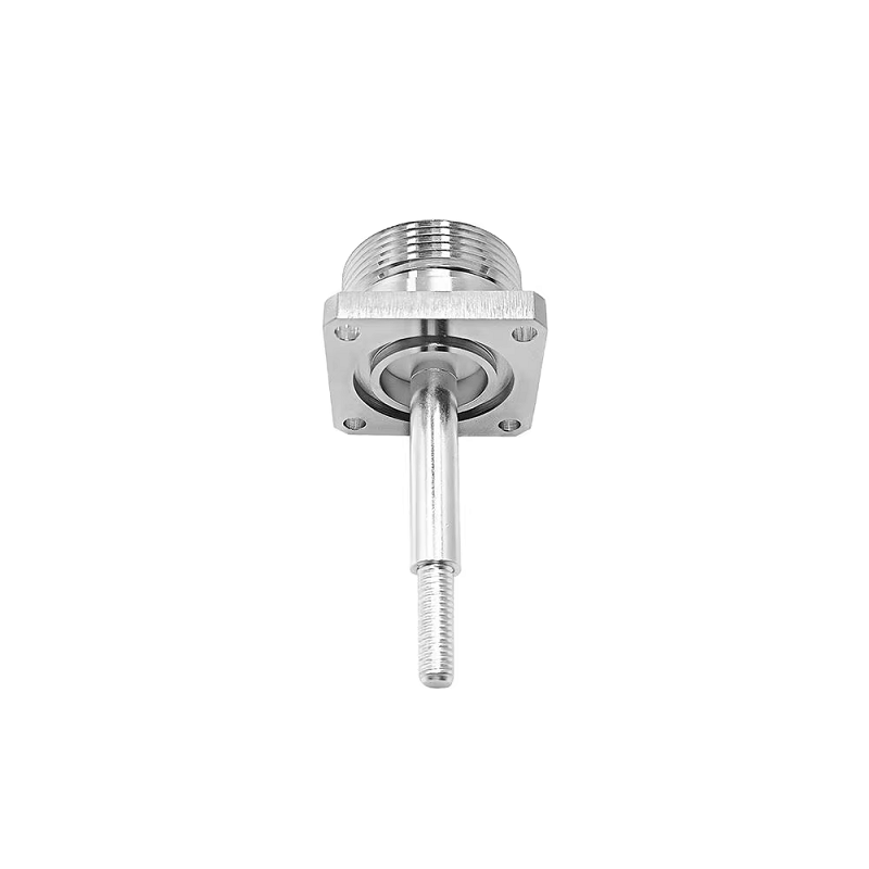
In high-power wireless telecommunications, signal integrity depends heavily on mechanical stability at every coaxial interface. While compact connectors work well inside shielded sub-assemblies, heavy-duty macro-cell sites, broadcast transmitters, and 5G base stations demand rugged hardware. The 7 16 rf connector, systematically recognized as the 7/16 DIN interface under IEC 61169-4 standards, remains a gold standard for demanding applications. Its physical dimensions—7 mm inner conductor diameter and 16 mm outer conductor diameter—provide the structural heft needed to handle high RF power, resist environmental exposure, and suppress passive intermodulation.
Deploying a 7 16 rf connector in field environments requires more than basic mechanical assembly. Achieving a stable, low-reflection joint requires precise cable preparation, absolute surface cleanliness, and calibrated torque control. Understanding how this interface operates alongside other common rf connector types ensures long-term link reliability across diverse cell sites and test installations.
Why 7/16 DIN Dominates Cellular Infrastructure
Modern multi-carrier cellular networks generate complex RF environments. When multiple high-power signals share a single transmission line, tiny non-linearities at connection points can generate unwanted interference. Passive intermodulation degrades receiver sensitivity, drops call capacity, and impairs data throughput across 4G and 5G spectrum bands.
The heavy-duty design of the 7 16 rf connector directly combats these challenges through several key mechanical features:
-
Massive Contact Surface Area: Large contact areas ensure low electrical resistance and uniform current distribution, preventing localized heating during high-power transmission.
-
High Contact Pressure: Robust threaded coupling nuts enable high torque values, creating tight metal-to-metal contact that eliminates micro-arcing and non-linear junction effects.
-
Environmental Sealing: Integrated O-rings and durable plating protect internal contact faces from moisture, dust, and atmospheric corrosion, preserving electrical properties over years of outdoor exposure.
These characteristics make the 7 16 rf connector essential for macro-cell feeder lines, remote radio heads, multi-band combiners, and tower-mounted amplifiers where equipment failure leads to costly field repair cycles.
Field Assembly Guidelines for High-Power Coaxial Cables
Installing a 7 16 din male connector onto corrugated copper or smooth-wall feeder cable requires methodical attention to detail. Improper strip dimensions, jagged copper edges, or metal filings trapped inside the interface can ruin an otherwise sound installation.
Precision Cable Stripping and Preparation
Always use manufacturer-specified stripping tools designed for the exact cable diameter and style being installed. Standard utility knives can score the inner conductor, create uneven copper outer conductors, or deform the dielectric. Trim the jacket cleanly and remove all copper flash or burrs. Dust off metal particles using a clean brush or lint-free wipe, as tiny metallic fragments trapped on the dielectric face will generate severe PIM once high RF power is applied.
Seating the Connector Body and Center Pin
Depending on whether the connector utilizes a clamp, crimp, or solder design, verify that the center conductor pin sits at the precise depth specified on the assembly drawing. A center pin that sits too far forward or recessed creates impedance discontinuities, driving up Voltage Standing Wave Ratio. Ensure the outer clamp mechanism engages uniformly around the corrugated outer conductor to maintain continuous 360-degree grounding.
Calibrated Torque Application
Never rely on feel or standard adjustable wrenches when tightening a high-power connector. Thread the coupling nut by hand first to ensure threads engage smoothly without cross-threading. Once seated, use a calibrated torque wrench to tighten the assembly to the exact manufacturer specification, typically between 25 and 30 Newton-meters for standard 7/16 interfaces. Under-tightening reduces contact pressure and invites moisture ingress, while over-tightening can distort the internal conductor spring fingers or strip coupling threads.
Comparing Heavy-Duty and Subminiature Interface Options
Selecting among different rf connector types requires balancing power handling, physical footprint, operational frequency range, and mechanical durability. Each connector family addresses specific operational priorities across an RF signal chain.
| Interface Feature | 7/16 DIN Interface | Type N Interface | SMA Interface |
| Physical Footprint | Heavy-duty / Large | Medium / Compact | Subminiature / Micro |
| Primary Focus | High Power & Low PIM | General RF Interconnect | Space-Constrained Equipment |
| Typical Frequency | DC to 7.5 GHz | DC to 11 GHz (or 18 GHz) | DC to 18 GHz (or higher) |
| Power Capacity | Multi-Kilowatt Handling | Moderate Power Levels | Low Power / Board Level |
| Primary Application | Feeder Cables & Antennas | Test Equipment & Base Units | Internal Modules & Transceivers |
While the 7 16 din male plug handles heavy power on tower tops, an rf sma connector serves a completely different purpose inside equipment chassis. The subminiature threaded SMA connector excels in high-density environments where physical space is limited and power levels remain low. However, attempting to adapt a small SMA interface directly into a high-power feeder run without intermediate attenuation or power control will lead to catastrophic thermal failure. Understanding where each connector family belongs prevents design mismatches across the system.
Controlling Passive Intermodulation and Reflection in the Field
Maintaining low VSWR and suppressing PIM requires ongoing discipline during both initial installation and routine site maintenance. Electrical performance can degrade rapidly if field crews neglect basic handling precautions.
Keep protective plastic caps installed on all open male and female interfaces until the exact moment of mating. Dust, rain, and airborne contaminants settling on silver-plated contacts create non-linear boundary layers. If an interface becomes contaminated, clean it thoroughly using approved electrical solvent and lint-free swabs—never scrub contact surfaces with abrasive pads or wire brushes, as removing silver or gold plating exposes underlying metals that oxidize quickly.
System maintenance procedures should include inspecting cable bend radii, supporting heavy feeder runs with proper line hangers, and applying secondary weatherproofing, such as cold-shrink tubing or butyl rubber tape, over all outdoor 7 16 rf connector joints. Physical strain on a connector joint disrupts internal contact alignment, raising reflection and degrading network performance over time.
Reliable Interconnect Engineering with Worldpeak
Building robust RF networks requires uncompromised manufacturing standards across every connector, jumper assembly, and adapter interface. A high-power base station setup is only as reliable as its weakest mechanical connection.
Worldpeak supports telecommunications operators, tower companies, and defense integrators worldwide with high-performance RF coaxial connectors, low-PIM jumper cables, and precision interconnect adapters. By combining precision CNC machining, specialized surface plating technologies, and rigorous factory testing, Worldpeak helps field engineers and system designers achieve low reflection, exceptional thermal handling, and stable low-PIM connections across demanding wireless infrastructure projects.





