 EN
EN

What environmental resistance can be customized for OEM rf cable
2026/09/25
Customize an rf high frequency cable for temperature, moisture, corrosion, vibration, flexing, and OEM validation needs.
2026/09/09
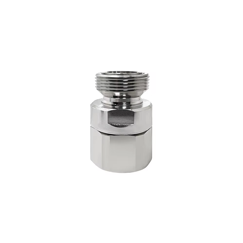
High-power wireless networks demand robust interconnect hardware capable of carrying significant RF power while maintaining minimal passive intermodulation. Selecting an optimal base station connector involves matching physical interface dimensions to operating frequency, weather resistance needs, and strict intermodulation limits. While modern cellular sites rely on the rugged 7/16 DIN connector (also known as the DIN 7-16) for main feeder connections, legacy systems occasionally attempt to utilize the older so239 connector. Understanding the engineering trade-offs between a high power RF connector like the DIN 7-16 and legacy interfaces ensures cellular equipment delivers maximum uptime and clean receiver sensitivity across dense network environments.
The 7/16 DIN connector derives its name from its precise physical dimensions: a 7 mm inner conductor pin coupled with a 16 mm inner diameter outer contact plane. This substantial contact surface area provides high current capacity and exceptional mechanical strength, making it a primary choice for high power RF connector applications in outdoor wireless sites.
Designed with a heavy-duty threaded coupling mechanism, the interface maintains constant contact pressure across ground planes. An internal fluoropolymer dielectric keeps characteristic impedance locked at 50 ohms up to 7.5 GHz. Integrated silicone O-rings provide IP68-rated weather sealing, protecting delicate internal contacts from water ingress and corrosion caused by severe environmental exposure on macro cell towers.
Evaluating whether an older so239 connector can support modern cellular equipment requires looking closely at frequency limits, power handling, and passive intermodulation behavior.
| Specification Parameter | 7/16 DIN Connector | SO239 Connector |
|---|---|---|
| Max Operating Frequency | Up to 7.5 GHz | Up to 300 MHz |
| Power Handling (@ 1 GHz) | ~820W CW | ~100W CW (Rapid drop-off above 300 MHz) |
| Typical PIM Performance | Exceeds −160 dBc | Not specified / Highly unpredictable |
| Weather Sealing Rating | IP68 (O-ring sealed) | Non-sealed (Requires external taping) |
| Characteristic Impedance | Constant 50 Ω | Non-constant (~50 Ω nominal at HF) |
| Typical System Deployment | 4G/5G base station connector builds | Legacy HF/VHF radio equipment |
Attempting to deploy an so239 connector in modern high-frequency cellular bands leads to high insertion loss, severe radiation leakage, and high standing wave ratios. The non-constant impedance profile of the so239 connector generates unwanted harmonics that severely degrade system performance at microwave frequencies.
Passive intermodulation (PIM) occurs when high-power RF signals pass through non-linear junctions in physical interconnects, generating interfering signals that fall directly into adjacent receiver bands. High-power multi-carrier cellular transmitters generate high peak power, making controlling PIM crucial for maintaining network capacity.
Substandard interfaces lacking controlled contact geometry generate elevated noise floors, causing dropped calls and reduced data throughput across cell sectors.
Proper field handling preserves the electrical advantages of a high power RF connector over long operational lifetimes on remote cell sites. Following consistent installation steps minimizes field maintenance visits and prevents water damage:
Strict adherence to these field installation procedures keeps base station connector assemblies operating reliably under harsh environmental conditions.
A mobile network operator executing a 5G mid-band overlay project faced severe receiver noise issues across several trial macro sites. Initial site audits revealed that field contractors had used legacy adapter harnesses containing so239 connector terminations to link high-power remote radio units with sector antennas.
Elevated PIM generated by the non-constant impedance junctions raised the uplink noise floor by 4 to 6 dB across adjacent cellular channels. Replacing the improper adapters with factory-tested 7/16 DIN connector jumpers immediately eliminated the intermodulation interference, restoring baseline receiver sensitivity and stabilizing data speeds across the entire coverage sector.
Matching the right base station connector format to specific equipment enclosures simplifies cable routing and reduces physical stress on cabinet bulkhead ports:
Selecting precision-machined bodies with durable silver contact plating guarantees reliable electrical performance across hundreds of field mating cycles.
Delivering low-PIM performance across high-power cellular infrastructure requires strict machining tolerances, advanced plating processes, and complete factory validation testing. Minor surface defects or inconsistent contact plating can lead to significant signal degradation and costly site downtime.
WORLDPEAK supports demanding wireless infrastructure projects by manufacturing high-performance 7/16 DIN connector products, specialized DIN 7-16 jumpers, and custom high power RF connector assemblies. Utilizing multi-axis CNC turning equipment, automated tri-metal plating lines, and automated PIM testing systems, WORLDPEAK supplies reliable base station connector solutions tailored for telecom operators and tower infrastructure managers worldwide. Every production lot undergoes 100% PIM and VSWR inspection, ensuring long-term operational reliability and superior signal clarity for next-generation mobile networks.

2026/09/25
Customize an rf high frequency cable for temperature, moisture, corrosion, vibration, flexing, and OEM validation needs.

2026/09/25
Streamline RF equipment assembly lines with custom coaxial jumpers. Reduce line-side rework, ensure precise routing, and boost production efficiency.

2026/09/25
Learn PL-259 connector selection, soldering, weatherproofing, and RF applications for dependable antenna feedlines.

2026/09/25
Confirm impedance for a 90 degree coax connector with an ODM test plan covering VNA setup, VSWR, acceptance criteria, and release records.

2026/09/25
Learn when an n type coax connector can omit extra anti-corrosion treatment and when OEM exposure conditions require it.

2026/09/25
Learn how the custom cable and wire sample process helps ODM buyers validate design, testing, and production readiness.