 EN
EN

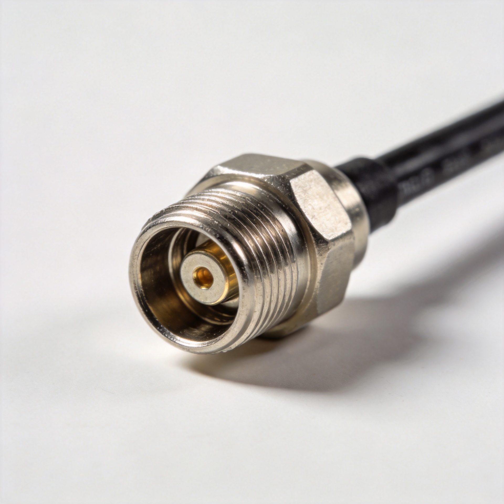
7/16 DIN Male: Low-PIM for Cellular Antennas
A 7 16 male connector is often selected where a cellular antenna path must carry substantial RF power without adding avoidable passive intermodulation. In a 4G or 5G feeder system, the connector is not an accessory: its contact geometry, torque, cleanliness, and interface match all influence the signal chain. For engineers evaluating a male coax connector, the useful question is not which interface is right in every installation. It is whether the site needs the mechanical scale and low-PIM discipline that a 7/16 interface is designed to support.
As an RF systems engineer, I start with frequency range and power level, then check the loss and PIM budget, and finally verify that the mechanical interface fits the outdoor installation. A 7 16 male connector belongs in that system-level review, especially on antenna feeders, remote radio runs, and high-power test paths where a marginal joint can be harder to diagnose than to prevent.
Why 7/16 DIN remains relevant in cellular RF
The 7/16 interface is a 50-ohm threaded RF connector family covered by IEC 61169-4. Its large mating geometry is one reason it is commonly associated with high-power cellular antenna systems and low intermodulation performance. That does not make every 7 16 male connector interchangeable: cable size, gender, plating, frequency rating, and environmental sealing still need to match the assembly specification.
Low PIM matters because nonlinear contact behavior can create unwanted mixing products when multiple carriers are present. A stable, clean, properly mated interface helps reduce the risk. In practical terms, a male coax connector for a multi-carrier antenna line should be chosen and installed as part of the full RF path, not simply by thread compatibility.
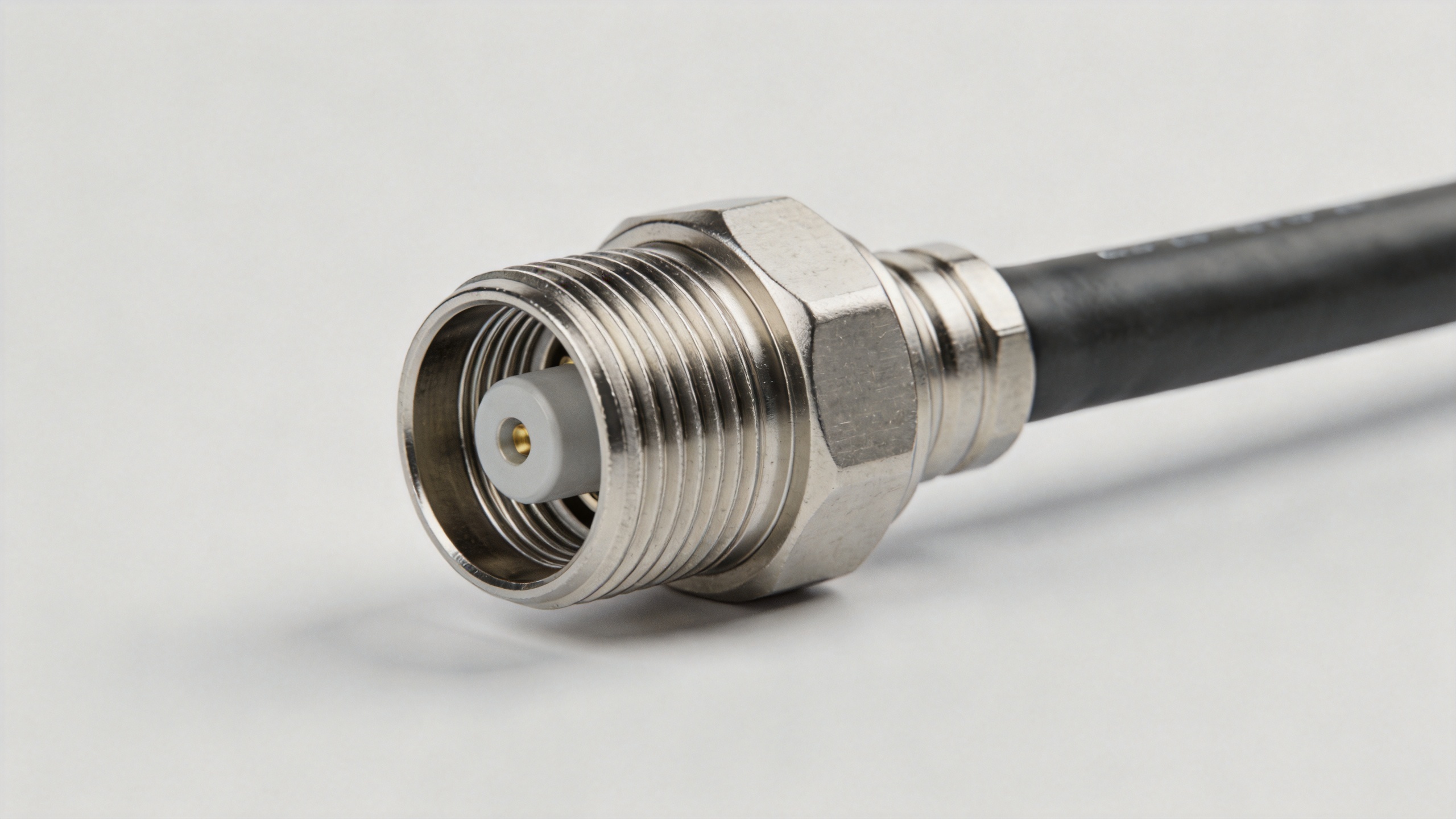
7/16 DIN versus N-type: use the application constraints
N-type remains a capable and widely used RF interface, particularly where its size, frequency options, and established cable ecosystem fit the design. The distinction is not cosmetic. When high forward power and stringent PIM control are central constraints, a 7 16 male connector is often the more appropriate interface to evaluate because its larger threaded contact system was developed for demanding antenna infrastructure.
| Selection criterion | 7/16 DIN | N-type |
|---|---|---|
| Typical decision context | High-power cellular feeders and low-PIM antenna paths | Broad RF installations where size and frequency needs fit the interface |
| Mechanical consideration | Large threaded coupling; confirm cable and access clearance | Smaller format; still requires correct torque and clean mating |
| Performance decision | Prioritize PIM discipline and power margin | Prioritize the confirmed assembly rating and system requirement |
If the primary constraint is high power at a cellular antenna, power handling and PIM margin should carry the most weight. If a compact assembly or a different frequency requirement dominates, an N-type design may be the better fit. Do not infer a system rating from the interface name alone. For example, the CMS-listed 7/16 DIN female to N male high-power RF connector is specified for 0–3.5 GHz and 3 kW at 2.5 GHz; those are product-specific values, not universal claims for every 7 16 male connector.
Where related male connector terms fit—and do not fit
Search terms can blur distinct interface families. A male coax connector is a broad description, while a 7 16 male connector identifies a particular threaded RF interface. An f connector male is commonly associated with 75-ohm video, CATV, or satellite distribution applications, so it should not be substituted into a 50-ohm cellular feeder simply because both parts are described as male connectors.
Likewise, a pl259 male connector is associated with the UHF connector family and serves different application conventions. Comparing an f connector male or a pl259 male connector with 7/16 DIN can clarify terminology, but it is not a basis for cross-substitution. Start with impedance, frequency, power, PIM requirement, and the mating interface specified by the radio, feeder, or antenna manufacturer.
Installation torque and field maintenance
A good electrical design can be undermined at the wrench. Use the torque value supplied by the connector or cable-assembly manufacturer, and use a calibrated torque wrench where the procedure calls for one. Overtightening can damage threads or distort the interface; undertightening can reduce contact consistency and allow movement. The exact torque is assembly-specific, so do not transfer a value from an N-type, f connector male, or pl259 male connector installation.
- Verify the mating interface, gender, impedance, cable type, and specified torque before assembly.
- Inspect threads and contact surfaces; keep metal chips, moisture, tape residue, and loose braid away from the mating plane.
- Support the cable so its bend and weight do not load the 7 16 male connector after tightening.
- For outdoor work, apply the approved weatherproofing method without trapping water at the joint.
- After commissioning, include visual inspection and RF sweep or PIM testing in the maintenance plan when the system requirement warrants it.
Field technicians sometimes focus only on whether a connector mates. Actually, that is only the first check. A male coax connector can look secure yet deliver inconsistent field performance if torque control, strain relief, or weather sealing was skipped. In vibration-prone or coastal locations, planned inspections are often more valuable than waiting for an intermittent fault.
A practical selection checklist
- Confirm the antenna-side interface requires a 7 16 male connector rather than a different connector family.
- Match the cable construction and termination method to the approved assembly.
- Review verified frequency, power, and environmental ratings for the exact product.
- Set a PIM target for the whole path, not just one component.
- Document torque, weatherproofing, test results, and replacement-part traceability.
For a connector reference, the CMS-listed RF-DIN-75A 7/16 connector lists a 75-ohm, 6 GHz, IP67 configuration. Because impedance is a system-level requirement, verify it against the intended cable and equipment rather than treating its name as a generic replacement for a 50-ohm antenna feeder part.
Conclusion
The right 7 16 male connector decision combines interface compatibility with real operating constraints: carrier loading, power, PIM sensitivity, cable mechanics, weather exposure, and maintenance access. Use a 7/16 DIN path when those requirements justify it, compare it with N-type on the verified assembly data, and keep unrelated terms such as f connector male and pl259 male connector in their proper application context. A disciplined installation and inspection process is what preserves the connector performance the specification was selected to achieve.





