 EN
EN

What environmental resistance can be customized for OEM rf cable
2026/09/25
Customize an rf high frequency cable for temperature, moisture, corrosion, vibration, flexing, and OEM validation needs.
2026/09/09
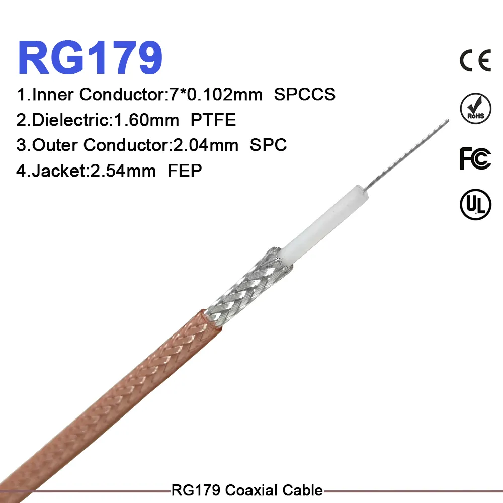
Choosing between different transmission line options requires matching characteristic impedance directly to system architecture. Across laboratory test benches, wireless infrastructure, broadcast bays, and high-definition production racks, selecting the right bnc coaxial cable setup dictates how cleanly high-frequency signals travel from source to load. While 50 ohm BNC and 75 ohm BNC options share similar physical footprints and bayonet coupling styles, their internal mechanics, power thresholds, and attenuation profiles serve completely different technical roles. Understanding these electrical trade-offs prevents standing wave reflections, signal loss, and expensive equipment troubleshooting in field installations.
Characteristic impedance is governed by the ratio between the outer diameter of the center conductor and the inner diameter of the outer shield, alongside the dielectric constant of the insulating layer. The physical geometry inside a bnc coaxial cable determines whether the line prioritizes maximum power transfer or minimal voltage attenuation.
Substituting one version for another alters physical dielectric ratios, introducing impedance mismatches that degrade overall link quality.
Evaluating performance parameters across both options highlights clear operational differences across power levels, attenuation rates, and typical cable group constructions.
| Performance Parameter | 50 Ohm BNC Coaxial Cable | 75 Ohm BNC Coaxial Cable |
|---|---|---|
| Primary System Focus | Maximum Power Handling & RF Stability | Minimal Signal Attenuation |
| Typical Attenuation @ 100 MHz | ~5.2 dB per 100 meters | ~4.1 dB per 100 meters |
| Typical Attenuation @ 1 GHz | ~18.5 dB per 100 meters | ~14.2 dB per 100 meters |
| Power Capacity @ 100 MHz | ~300 Watts CW | ~150 Watts CW |
| Common Cable Types | RG-58, RG-142, RG-213, LMR-195 | RG-59, RG-6, RG-11, Belden 1855A |
| Dielectric Contact Profile | Thicker outer dielectric mass | Reduced dielectric insulation at interface |
| Core Operational Domain | RF testing, wireless antennas, telecom | SDI video cable paths, HD broadcast, CCTV |
Using a 50 ohm bnc to bnc cable for high-powered RF transmission ensures low standing wave ratios, while deploying a 75 ohm bnc to bnc cable across video distribution setups preserves pristine signal clarity over extended routing paths.
Modern digital video routing relies heavily on strict 75-ohm impedance matching to maintain high data throughput without jitter or frame dropping. Serial Digital Interface protocols—ranging from HD-SDI up to 3G, 6G, and 12G 4K Ultra-HD standards—require flat frequency responses up to 12 GHz.
In a high-definition video distribution path, deploying improper 50-ohm interconnects creates localized impedance steps at every connector junction. Signal reflections bounce back along the transmission line, causing phase distortion, severe return loss spikes, and eye-diagram degradation. Utilizing dedicated 75-ohm bnc coaxial cable harnesses with optimized 75-ohm connector pins maintains precise signal geometry, preventing packet errors across critical broadcast production feeds.
System integrators frequently ask whether 50-ohm and 75-ohm BNC hardware can intermate without damaging physical components or causing system failures.
Applying strict color labeling and clear physical separation across mixed signal racks minimizes field installation errors and keeps operational uptime high.
A commercial production facility undergoing a studio upgrade experienced severe signal jitter and intermittent frame drops across uncompressed 3G-SDI video feeds. Initial technical audits revealed that maintenance crews had inadvertently installed generic 50-ohm bnc to bnc cable jumpers between routing switchers and master control panels during a previous equipment move.
Replacing the improper 50-ohm jumpers with precision-engineered 75-ohm SDI video cable assemblies resolved the impedance step-down issues completely. Post-installation testing confirmed crisp eye-pattern openings, zero frame drops, and sub-1.12:1 VSWR performance across every 1080p video routing channel.
Maintaining signal integrity across complex communications networks requires strict dimensional controls, high-grade plating materials, and 100% factory inspection testing. Inconsistent dielectric machining or loose center contact tolerances cause sudden return loss spikes at high frequencies.
WORLDPEAK supports demanding RF and broadcast infrastructure projects by manufacturing a comprehensive selection of 50 ohm BNC and 75 ohm BNC products, custom bnc to bnc cable assemblies, precision bnc coaxial cable lines, and high-frequency SDI video cable solutions. Utilizing multi-axis CNC turning centers, automated soldering and crimping equipment, and precise gold-plating processes, WORLDPEAK delivers custom cable assemblies tailored to exact length and jack requirements. Every production lot undergoes complete VSWR, insertion loss, and continuity testing, ensuring reliable performance, long-term durability, and outstanding value for telecom operators, broadcast engineers, and industrial system integrators worldwide.

2026/09/25
Customize an rf high frequency cable for temperature, moisture, corrosion, vibration, flexing, and OEM validation needs.

2026/09/25
Streamline RF equipment assembly lines with custom coaxial jumpers. Reduce line-side rework, ensure precise routing, and boost production efficiency.

2026/09/25
Learn PL-259 connector selection, soldering, weatherproofing, and RF applications for dependable antenna feedlines.

2026/09/25
Confirm impedance for a 90 degree coax connector with an ODM test plan covering VNA setup, VSWR, acceptance criteria, and release records.

2026/09/25
Learn when an n type coax connector can omit extra anti-corrosion treatment and when OEM exposure conditions require it.

2026/09/25
Learn how the custom cable and wire sample process helps ODM buyers validate design, testing, and production readiness.