 EN
EN

7/16 DIN Connector Guide: High-Power RF Standard
2026/09/24
Choose a 7 16 connector for high-power RF: compare DIN and Type N, protect PIM margin, and apply field installation checks.
2026/08/25
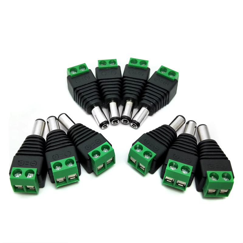
Coaxial architecture often needs to double its workload. In modern security setups, active antenna arrays, and remote radio feeds, running separate lines for data transmission and DC operational current wastes physical space and bloats installation budgets. Passing direct current directly alongside radio frequency or video telemetry over a single coaxial cable line solves this hardware bottleneck cleanly.
Achieving reliable power delivery across standard coax depends on choosing the correct interface assembly. Integrating a dedicated bnc dc connector or incorporating an active bnc power injector requires a clear understanding of impedance matching, frequency isolation, and component thermal limits. Choosing the wrong connector variation or ignoring board-level current paths leads to poor performance, signal degradation, and unexpected equipment failure.
Standard coaxial transmission lines are designed to pass alternating current waveforms within designated RF bands while maintaining a constant characteristic impedance, typically 50 ohms or 75 ohms. Introducing direct current into this signal path requires a clear split between the high-frequency alternating current and steady-state DC power. In a standard bias network setup, the power source feeds DC directly into the bias network, where it joins the incoming RF signal before flowing out through the coaxial cable as a combined signal and power path.
This isolation relies on fundamental reactive principles:
Inductive Blocking: High-frequency inductors (chokes) allow low-frequency DC current to enter the line while presenting high impedance to the returning RF energy.
Capacitive Isolation: Series capacitors block DC voltage from feeding backward into sensitive processing hardware while letting high-frequency RF signals pass cleanly.
When this isolation network is built directly into an inline housing or specialized adapter, the resulting component acts as a functional bnc dc bias interface or inline injection node. The primary objective is keeping power completely clean. If switching noise, ripple voltage, or ground loops bleed onto the central signal pin, visible horizontal hum bars appear on analog video feeds, and high bit-error rates degrade digital telemetry.
Using one cable run for power and data saves money, cuts down on panel penetrations, and simplifies installation in tight equipment racks or outdoor enclosures.
| Application | Primary Functional Component | Core Advantage |
| CCTV Systems | BNC Power Injector | Single RG59/RG6 run for video & 12V power |
| Active Antennas | BNC DC Bias Tee | Powers remote LNAs over the main feedline |
| GPS & Marine | Inline BNC DC Connector | Delivers clean DC to remote signal splitters |
CCTV and Video Surveillance: Combining 12V or 24V direct current with high-definition video over RG59 or RG6 coaxial runs keeps camera installations clean and cuts installation labor in half.
Active Antennas and Masthead Amplifiers: Remote Low-Noise Amplifiers (LNAs) mounted high on towers or exterior masts require local operational power. Injecting power directly onto the coaxial feedline eliminates the need for expensive secondary power drops up the tower.
Marine and Remote GPS Systems: Active GPS receivers and antenna splitter nodes rely on inline DC injection to drive internal amplification chips without requiring dedicated power lines through waterproof bulkheads.
Integrating DC power paths directly onto internal system boards changes how hardware engineers design front panels and interface cards. Rather than using external inline bias tees, modern video servers, base stations, and receiver hubs handle power isolation directly on the main circuit board using a dedicated pcb mount bnc connector. These connectors come in several structural styles, including vertical mount, right-angle mount, and edge mount configurations to fit different panel orientations.
When specifying a pcb mount bnc connector for lines carrying DC, several design considerations come into play:
Current-Carrying Capacity: Center contacts and trace connection pins must handle the system's continuous operating current without overheating or degrading the center pin mating pressure over long deployment cycles.
Dielectric Spacing and Creepage: The physical gap between the center power pin and the grounded outer shell must meet safety guidelines for the maximum expected system voltage, especially during voltage spikes.
Mechanical Board Retention: Coaxial cables exert strong leverage on panel connectors. Using sturdy through-hole solder posts or threaded bulkhead locknuts prevents mechanical stress from cracking solder joints or lifting delicate PCB traces.
Impedance Consistency: The internal contact geometry must maintain a clean 50-ohm or 75-ohm profile through the board transition to avoid unwanted signal reflections.
System failures during site commissioning usually come down to a few basic oversights during component selection and installation.
Confusing Injection with Isolation: A bnc power injector introduces power into the line, whereas a bnc connector dc block does the exact opposite—it intentionally blocks direct current while letting the RF signal pass safely through. Installing a DC block when the downstream equipment requires remote power cuts off the device entirely.
Ignoring Voltage Polarity: Most low-voltage DC setups use a positive-center pin configuration. Reversing polarity on raw-wire power injectors risks instantly damaging sensitive receiver inputs or active antenna modules.
Overloading Center Pin Contacts: Exceeding the maximum rated current causes contact resistance to build up heat at the center pin interface. Over time, this thermal cycling degrades plating quality, introduces signal noise, and leads to intermittent power dropouts.
Building reliable coaxial power injection systems requires tight tolerance manufacturing, low-loss dielectric materials, and long-term mechanical durability. Minor variations in pin length, plating thickness, or contact tension between different suppliers can ruin high-frequency performance or cause physical connection failures in the field.
Working with experienced RF connector manufacturing partners makes a massive difference in project consistency. Leading coaxial interface manufacturers maintain complete control over precision CNC machining, electroplating processes, and automated assembly line testing. Maintaining strict quality standards like ISO9001 certification and compliance with international standards such as CE, RoHS, and UL94 guarantees that every bnc dc connector batch delivers consistent electrical performance.
From high-volume commercial production runs to specialized custom hardware assemblies, partnering with an established supplier like Worldpeak simplifies sourcing across expansive component catalogs. Access to comprehensive in-house testing—including insertion loss benchmarking, return loss testing, and high-voltage dielectric isolation verification—gives engineers full confidence that their connector selection will perform flawlessly in the field.
Frequently Asked Questions
How does a bnc dc connector differ from a bnc connector dc block?
A bnc dc connector or bias network active port allows DC power to pass alongside the high-frequency signal down the coaxial line. In contrast, a bnc connector dc block contains internal capacitive isolation that stops DC voltage completely while letting the high-frequency AC or video signal pass through undamaged.
Can a standard pcb mount bnc connector handle continuous DC power?
Yes, provided the connector's current rating exceeds the operating load. Always check the manufacturer's thermal and current specs, and ensure the circuit board layout provides adequate heat dissipation and isolation spacing around the solder pins.
What voltage levels do common inline power injectors support?
Commercial video surveillance and remote RF setups typically use 12V or 24V DC injection lines. Industrial setups may run higher voltages to compensate for long cable resistance drops. Always verify component ratings before applying power to the line.

2026/09/24
Choose a 7 16 connector for high-power RF: compare DIN and Type N, protect PIM margin, and apply field installation checks.

2026/09/24
Compare TNC connector types, specs and applications, including RP-TNC, bulkhead options, vibration performance and adapter selection.

2026/09/24
Understand MMCX connector basics, RF limits, and how to choose the right coaxial interface for compact systems.

2026/09/24
Understand RP-SMA connector polarity, mating rules, frequency checks, and OEM termination options for reliable RF builds.

2026/09/24
Choose the right bnc male connector for RF, CCTV and test systems with clear 50Ω vs 75Ω, type and installation guidance.

2026/09/24
Compare LMR400 specs, cable loss, uses, connectors and RG8/RG213 alternatives with a practical RF loss-budget method.