 EN
EN

What environmental resistance can be customized for OEM rf cable
2026/09/25
Customize an rf high frequency cable for temperature, moisture, corrosion, vibration, flexing, and OEM validation needs.
2026/09/09
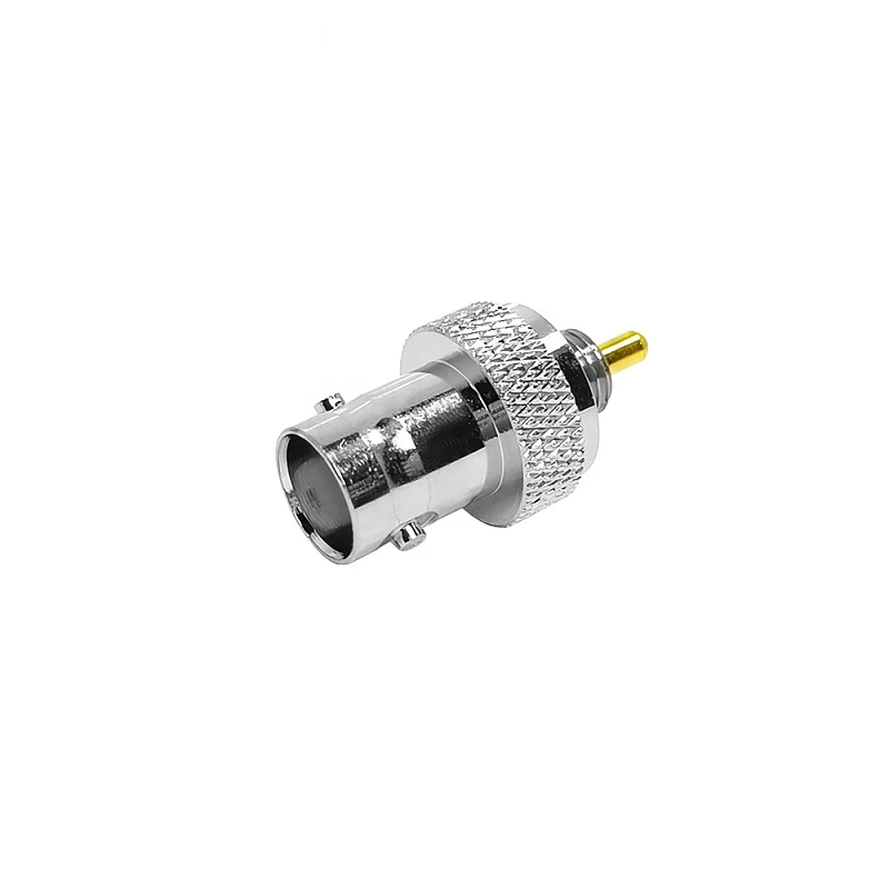
Finding a dependable RF coupling interface involves balancing fast installation speed against mechanical longevity, shielding performance, and electrical impedance stability. Across broadcast production bays, test instrumentation benches, and industrial telemetry setups, bnc male connectors remain a foundational standard for quick-connect coaxial terminations. Evaluating whether to deploy a streamlined BNC crimp connector assembly or a traditional BNC clamp termination scheme often dictates field serviceability, pull-off strength, and long-term signal clarity. Understanding key BNC connector types, proper assembly methods, and system design variables ensures smooth coaxial cable male to female routing in demanding production environments.
The defining structural feature of bnc male connectors is the classic bayonet coupling shell, engineered to lock securely onto female panel jacks via a rapid quarter-turn rotation. Internal spring-loaded locking pins deliver constant mating pressure on ground planes, preventing sudden signal dropouts caused by cabinet vibration or physical cable tugs.
Standard bnc male connectors come in two distinct characteristic impedance options tailored for specific transmission tasks:
Connecting a 50-ohm plug directly to a 75-ohm jack or forcing mismatched coax runs into a coaxial cable male to female junction creates continuous standing wave reflections. Over extended cable paths, impedance discontinuities degrade return loss and introduce signal jitter across sensitive digital video or high-frequency data streams.
Selecting between factory-style crimping and manual clamp mechanics requires evaluating production volume limits, technician tooling budgets, and field service requirements.
| Performance Characteristic | BNC Crimp Connector | BNC Clamp Termination |
|---|---|---|
| Typical Assembly Time | ~30 to 45 seconds per end | ~2 to 4 minutes per end |
| Required Tooling Gear | Calibrated ratcheting hex crimper | Basic hand spanners & solder iron |
| Cable Pull Strength | Excellent (>80 lbs retention) | Moderate (>50 lbs retention) |
| Field Reusability | Non-reusable (single crimp) | Fully reusable component parts |
| Typical Return Loss @ 2 GHz | Sub-1.15:1 VSWR | Sub-1.20:1 VSWR |
| Best Operational Fit | High-volume cable harness builds | On-site repairs & remote field setups |
While BNC clamp termination methods offer convenient field service options when working without specialized hand tools, high-volume manufacturing lines lean toward BNC crimp connector workflows. Ratcheting crimp tools compress hex ferrules onto braided shields with uniform mechanical force, driving down assembly failure rates and guaranteeing consistent impedance across extensive cable production runs.
Achieving consistent return loss and maximum mechanical grip during BNC crimp connector installation requires strict adherence to precise stripping dimensions and proper handling techniques:
A regional television production studio recently completed a comprehensive facility upgrade involving 240 SDI video feed lines running through dense routing racks. The existing installation relied on aging BNC clamp termination fittings that had loosened over five years of operational thermal cycling, causing intermittent packet loss on uncompressed HD video feeds.
Re-terminating all critical coaxial cable male to female interconnections with high-precision BNC crimp connector units stabilized signal propagation across every line. Subsequent post-installation testing with 3G-SDI pattern generators confirmed clean eye diagrams, zero frame drops, and sub-1.12:1 VSWR performance across all broadcast video routing channels.
Matching specific BNC connector types against different coaxial cable dimensions ensures stable signal transmission and prevents mechanical binding during installation:
Selecting quality precision-machined bodies with durable nickel outer plating protects against thread galling and mechanical wear across hundreds of insertion cycles.
Delivering long-term signal stability across complex communication networks requires strict dimensional controls, high-grade plating materials, and 100% factory inspection testing. Inconsistent machining on bayonet lugs or center pins leads to intermittent ground contacts and elevated return loss at higher operating frequencies.
WORLDPEAK supports demanding RF interconnect requirements by manufacturing a comprehensive selection of bnc male connectors, custom coaxial cable male to female jumpers, BNC crimp connector variants, and durable BNC clamp termination solutions. Utilizing automated CNC turning centers, precise gold-plating lines, and automated assembly equipment, WORLDPEAK delivers 50-ohm and 75-ohm connector solutions tailored for broadcast, telecom, and industrial test instrumentation. Every production batch undergoes rigorous VSWR and insertion loss validation, ensuring reliable quality and exceptional signal integrity for system integrators worldwide.

2026/09/25
Customize an rf high frequency cable for temperature, moisture, corrosion, vibration, flexing, and OEM validation needs.

2026/09/25
Streamline RF equipment assembly lines with custom coaxial jumpers. Reduce line-side rework, ensure precise routing, and boost production efficiency.

2026/09/25
Learn PL-259 connector selection, soldering, weatherproofing, and RF applications for dependable antenna feedlines.

2026/09/25
Confirm impedance for a 90 degree coax connector with an ODM test plan covering VNA setup, VSWR, acceptance criteria, and release records.

2026/09/25
Learn when an n type coax connector can omit extra anti-corrosion treatment and when OEM exposure conditions require it.

2026/09/25
Learn how the custom cable and wire sample process helps ODM buyers validate design, testing, and production readiness.