 EN
EN

7/16 DIN Connector Guide: High-Power RF Standard
2026/09/24
Choose a 7 16 connector for high-power RF: compare DIN and Type N, protect PIM margin, and apply field installation checks.
2026/09/12
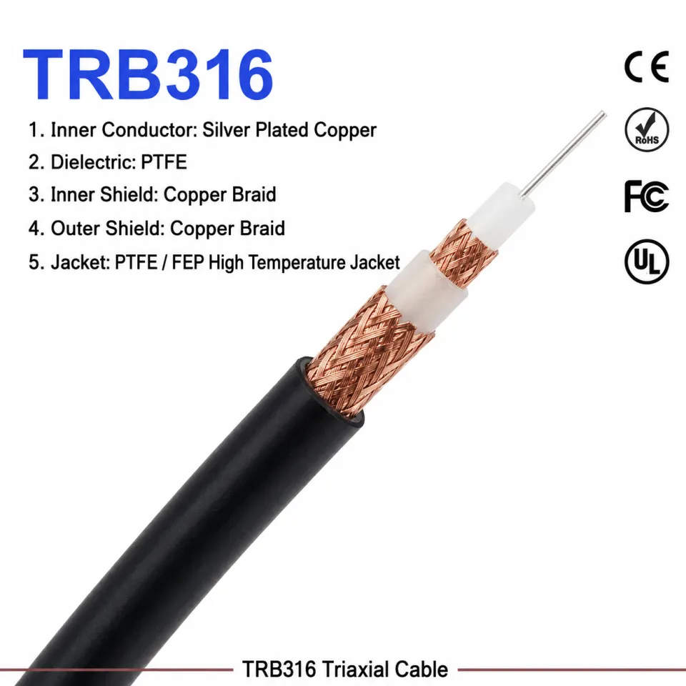
Extending base station feeds or outdoor wireless access points frequently introduces signal attenuation, mechanical strain, and impedance mismatches. Implementing a high-precision coax adapter cable ensures minimal signal degradation when bridging long transmission distances. Field engineers often encounter situations where rigid primary feeder lines cannot interface directly with sensitive terminal electronics, making an antenna run extension necessary for system integration.
Using an improperly rated RF coaxial adapter or poorly shielded jumper line can trigger high Voltage Standing Wave Ratio (VSWR) reflections, leading to transmitter power loss and receiver sensitivity drops. Specifying a factory-tested SMA to N-type coax jumper fabricated from durable low-loss antenna cable guarantees physical strain relief while preserving link budget integrity across sub-6 GHz spectrums. WORLDPEAK engineers high-performance interconnect components and cable assemblies for industrial wireless infrastructure. This guide covers the technical parameters, insertion loss calculations, strain relief protocols, and factory quality standards required when choosing a robust coax adapter cable solution.
Connecting heavy 1/2-inch or 7/8-inch corrugated feeder lines directly to compact transceivers risks tearing surface-mount SMA or micro-coaxial (U.FL/IPEX) connectors off printed circuit boards. Integrating a flexible coax adapter cable acts as a physical shock absorber, isolating PCB solder joints from wind-induced cable vibration and thermal expansion stress.
Key Technical Functions of Extension Adapters:
Interface Bridging: Converts large-format industrial interfaces (such as N-type, 7/16 DIN, or 4.3-10) down to compact module interfaces using an SMA to N-type coax transition assembly.
Flexibility & Routing: Replaces stiff corrugated copper with flexible stranded-core low-loss antenna cable for tight enclosure routing and clean cabinet installations.
Connector Wear Protection: Serves as a sacrificial interface element during routine maintenance, protecting expensive fixed radio chassis connectors from repeated mating cycle wear.
VSWR Stability: Precision impedance matching across an RF coaxial adapter prevents signal reflection bottlenecks at critical interconnect junctions during an antenna run extension.
Selecting the correct coaxial diameter and shielding structure directly impacts signal retention and physical flexibility. The comparison below outlines common cable choices for an antenna run extension project:
| Parameter | RG-58 Flex Cable | LMR-200 Equivalent | LMR-400 Low-Loss Equivalent |
| Outer Diameter (OD) | 4.95 mm (0.195 in) | 4.95 mm (0.195 in) | 10.29 mm (0.405 in) |
| Shielding Type | Bare Copper Braid (85%) | Aluminum Foil + Tinned Braid (100%) | Aluminum Foil + Tinned Braid (100%) |
| Attenuation @ 2.4 GHz | ~68 dB / 100m | ~39 dB / 100m | ~22 dB / 100m |
| Attenuation @ 5.8 GHz | ~112 dB / 100m | ~62 dB / 100m | ~35 dB / 100m |
| Min. Bend Radius | 25 mm | 25.4 mm | 25.4 mm (Single), 101.6 mm (Repeated) |
| Primary Use Case | Short internal cabinet jumpers | Mid-distance indoor coax adapter cable | High-power outdoor low-loss antenna cable |
While RG-58 offers high mechanical flexibility, its thin dielectric leads to significant RF power loss at microwave frequencies. For outdoor installations, specifying an LMR-400 class low-loss antenna cable combined with a factory-crimped SMA to N-type coax adapter ensures optimal power transmission to distant antennas.
Calculating cumulative insertion loss is mandatory before deploying an antenna run extension in long-range IoT, 4G LTE, or 5G NR networks. System loss is determined by combining cable attenuation per meter with individual connector interface losses.
Total Extension Loss Equation:
Practical Engineering Guidelines:
Connector Loss Allowance: Budget 0.1 dB to 0.15 dB of loss for every precision RF coaxial adapter interface operating below 6 GHz.
Frequency Dependency: Signal loss scales non-linearly with frequency. A coax adapter cable that exhibits negligible loss at 900 MHz ISM bands can cause significant attenuation when operating at 5.8 GHz Wi-Fi frequencies.
Impedance Continuity: Ensure every component—including the low-loss antenna cable, connectors, and inline surge arrestors—maintains a strict 50-ohm characteristic impedance to prevent standing wave reflections.
To prevent water ingress, signal noise, and field failures in critical telecom installations, WORLDPEAK applies stringent manufacturing and testing protocols to every coax adapter cable:
Helium Leakage & IP68 Weatherproofing: Outdoor SMA to N-type coax jumpers utilize inner adhesive heat-shrink tubing and O-ring silicone seals to guarantee IP68 submersion protection against rain and moisture.
Vector Network Analyzer (VNA) Testing: 100% of manufactured cable assemblies undergo automated VNA sweeps to confirm return loss (VSWR <= 1.15) and insertion loss compliance across target operational bands.
Gold-Plated Contact Durability: Center pins are electroplated with 30 micro-inches of gold over beryllium copper, ensuring high mating durability and low contact resistance across 500+ connection cycles.
Passive Intermodulation (PIM) Screening: Low-PIM variants are tested down to <= -155 dBc @ 2 x 20W to eliminate inter-channel interference in multi-carrier DAS deployments utilizing an RF coaxial adapter.
WORLDPEAK provides global integrators and equipment manufacturers with custom-engineered jumper solutions tailored for demanding outdoor deployments:
Tailored Cable Lengths: Custom cut lengths from 0.1 meters to over 50 meters, pre-tested for specialized antenna run extension setups.
Custom Connector Configurations: Wide selection of straight, right-angle, bulkhead, and panel-mount interfaces including SMA, N-type, TNC, BNC, 4.3-10, and 7/16 DIN.
Low MOQ & Rapid Prototyping: Flexible Minimum Order Quantities for OEM orders with sample dispatch available within 3 to 5 business days.
Full Compliance Verification: All raw materials comply with RoHS, REACH, and ISO9001 quality system directives.
For detailed engineering drawings, datasheets, or custom quotation requests, explore the product catalog at

2026/09/24
Choose a 7 16 connector for high-power RF: compare DIN and Type N, protect PIM margin, and apply field installation checks.

2026/09/24
Compare TNC connector types, specs and applications, including RP-TNC, bulkhead options, vibration performance and adapter selection.

2026/09/24
Understand MMCX connector basics, RF limits, and how to choose the right coaxial interface for compact systems.

2026/09/24
Understand RP-SMA connector polarity, mating rules, frequency checks, and OEM termination options for reliable RF builds.

2026/09/24
Choose the right bnc male connector for RF, CCTV and test systems with clear 50Ω vs 75Ω, type and installation guidance.

2026/09/24
Compare LMR400 specs, cable loss, uses, connectors and RG8/RG213 alternatives with a practical RF loss-budget method.