 EN
EN

7/16 DIN Connector Guide: High-Power RF Standard
2026/09/24
Choose a 7 16 connector for high-power RF: compare DIN and Type N, protect PIM margin, and apply field installation checks.
2026/09/10
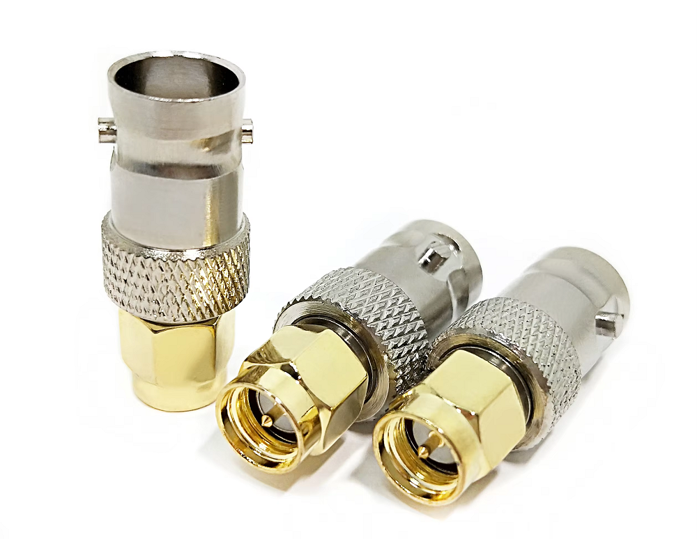
Coaxial cable networks form the fundamental transmission lines for RF communication systems, test benches, broadcast facilities, and mobile base stations. Maintaining signal integrity across complex feedlines often requires joining separate cable segments or changing interface genders. At the center of these connections sits the coax to coax adapter, often referred to in field applications as a barrel connector or inline coaxial coupler.
While a coax to coax adapter appears to be a basic passive component, its internal mechanical precision and electrical symmetry play a vital role in preventing signal degradation. Every junction added to an RF signal path introduces potential insertion loss, return loss, and impedance discontinuities. Understanding how to select the right barrel connector, evaluate loss parameters, and minimize junction reflections ensures system performance remains stable across demanding frequency bands.
A standard coax to coax adapter features a female-to-female or male-to-female interface engineered to join two coaxial cable assemblies end-to-end. By extending total line reach without requiring custom continuous cabling, a barrel connector provides operational flexibility during field installations and laboratory test reconfigurations.
A high-performance coaxial coupler maintains continuous 50-ohm or 75-ohm characteristic impedance across its internal mating contacts. The center contact socket must grip the mating pin firmly, while the outer conductor shell ensures seamless 360-degree shield continuity. This double-ended structure protects against electromagnetic interference leakage and maintains stable transmission parameters.
Selecting the proper barrel connector depends heavily on the operating frequency band, power requirements, and mechanical stress environment of the application:
| Connector Interface | Maximum Frequency | Typical Insertion Loss | Primary Industrial Application |
|---|---|---|---|
| BNC Barrel | Up to 4 GHz | ~0.15 dB @ 2 GHz | Test Equipment, Video Feedlines, CCTV |
| SMA Barrel | Up to 18 GHz | ~0.10 dB @ 10 GHz | Microwave Systems, Radar, RF Test Benches |
| N-Type Barrel | Up to 11 GHz | ~0.08 dB @ 6 GHz | Outdoor Wireless Infrastructure, Base Stations |
| TNC Barrel | Up to 18 GHz | ~0.12 dB @ 10 GHz | Avionics, Military, High-Vibration Settings |
| 7/16 DIN Barrel | Up to 7.5 GHz | ~0.05 dB @ 3 GHz | High-Power Cellular Towers, Macro Cells |
Higher-frequency interfaces like SMA and TNC utilize precision dielectric materials and tighter thread tolerances to preserve tight Standing Wave Ratios (VSWR) up to 18 GHz. In contrast, heavy-duty N-Type and 7/16 DIN couplers prioritize high power handling, weatherproofing seals, and mechanical ruggedness for outdoor base station towers.
Understanding the distinction between an RF extension component and an active interface conversion unit prevents serious system architecture mistakes. A coax to coax adapter functions entirely in the analog RF domain, providing a passive metallic path that transfers radio frequency energy between matching transmission lines without altering signal characteristics.
A coax to usb adapter belongs to an entirely different hardware category. Rather than simply connecting coaxial cables, a coax to usb adapter bridges analog RF signals directly into digital computing environments. Common examples include Software-Defined Radio (SDR) receivers, digital TV tuners, and compact USB spectrum analyzer dongles.
These active devices house internal Low-Noise Amplifiers (LNAs), analog-to-digital converters (ADCs), and USB controller microchips within their housing. Many models also incorporate a bias tee network to supply DC voltage up the coaxial line to power active external antennas. While a passive barrel connector merely passes high-frequency signals along an RF extension, an active USB converter processes and translates analog RF energy into digital data streams.
Every coax to coax adapter added to a signal path introduces a subtle physical bump in the transmission line geometry. Even top-tier couplers introduce approximately 0.1 dB to 0.3 dB of insertion loss per junction. More critically, impedance variations at the connection points increase overall system VSWR, reflecting a portion of the RF energy back toward the transmitter.
Consider a production testing environment where multiple short jumper cables join together via three series-connected BNC barrel connectors. Testing the cumulative effect of these three inline junctions shows a measurable signal drop: total insertion loss increases by roughly 0.5 dB, while system VSWR degrades from 1.08:1 to 1.18:1 at 2.4 GHz.
In high-frequency or long-distance RF distribution systems, cascading multiple passive adapters creates compounding reflection points. Minimizing the total number of intermediate junctions and opting for continuous single-run cables wherever possible preserves transmission fidelity and reduces retest errors caused by loose fittings.
During a high-volume manufacturing deployment for cellular IoT modules, an automated test fixture suffered from inconsistent measurement results and higher-than-expected retest failure rates. Inspection of the test harness revealed six inline BNC coax to coax adapter points placed between the Device Under Test (DUT) and the vector signal analyzer.
The multiple adapter junctions introduced intermittent contact resistance during rapid, high-cycle robotic plugging. By redesigning the internal harness architecture with custom-length direct cable assemblies, field engineers eliminated four intermediate couplers, reducing the total junction count to just two precision interfaces.
This simplified RF extension setup reduced overall signal loss by 0.6 dB across the LTE frequency bands and stabilized VSWR readings. The resulting signal reliability boosted overall factory test station throughput by 12% by eliminating false failure retests.
Proper handling and maintenance of intermediate coaxial couplers prolongs equipment life and ensures repeatable electrical performance:
Delivering stable, low-loss interconnects requires advanced manufacturing techniques, high-purity alloy selection, and tight quality assurance processes. Microscopic variations in contact plating thickness or internal dielectric alignment directly impact performance at higher gigahertz frequencies.
Worldpeak meets these strict industrial demands through advanced CNC machining, automated plating processes, and complete RF characterization testing. Supplying a comprehensive range of coax to coax adapter products, precision barrel connector models, coaxial coupler series, and specialized RF extension hardware, Worldpeak utilizes premium materials including beryllium copper center contacts, solid brass bodies, heavy gold or silver plating, and high-purity PTFE insulators.
Every Worldpeak coaxial coupler undergoes rigorous testing to guarantee VSWR ratings below 1.15:1 at designated operating limits. Whether engineering complex aerospace test systems, building cellular infrastructure, or sourcing custom interconnect components, partnering with a proven RF manufacturer like Worldpeak guarantees long-term transmission reliability across every link in your signal path.

2026/09/24
Choose a 7 16 connector for high-power RF: compare DIN and Type N, protect PIM margin, and apply field installation checks.

2026/09/24
Compare TNC connector types, specs and applications, including RP-TNC, bulkhead options, vibration performance and adapter selection.

2026/09/24
Understand MMCX connector basics, RF limits, and how to choose the right coaxial interface for compact systems.

2026/09/24
Understand RP-SMA connector polarity, mating rules, frequency checks, and OEM termination options for reliable RF builds.

2026/09/24
Choose the right bnc male connector for RF, CCTV and test systems with clear 50Ω vs 75Ω, type and installation guidance.

2026/09/24
Compare LMR400 specs, cable loss, uses, connectors and RG8/RG213 alternatives with a practical RF loss-budget method.