 EN
EN

What environmental resistance can be customized for OEM rf cable
2026/09/25
Customize an rf high frequency cable for temperature, moisture, corrosion, vibration, flexing, and OEM validation needs.
2026/09/02
Finding the right coaxial connector often feels like navigating a maze of mechanical dimensions, power tolerances, and frequency limits. Choose wrong, and you risk impedance mismatches, signal reflections, line attenuation, or complete field hardware failure.
Selecting an RF connector involves balancing mechanical robustness, physical envelope constraints, signal integrity, and environmental resistance. Below is an in-depth breakdown of seven essential coaxial connector families, their core specs, and a structured decision matrix for practical system design.
BNC connectors are standard across benchtop test gear, legacy networking, and video systems.
Operating Frequency: DC to 4 GHz (standard), up to 12 GHz in precision variants.
Impedance: Available in 50 Ω and 75 Ω versions.
Coupling Mechanism: Push-and-twist bayonet lock.
Best Applications: Oscilloscopes, lab test leads, CCTV, and broadcast SDI connections.
Pros: Rapid quick-connect mating, low cost, widely adopted.
Cons: Poor mechanical stability under severe vibration; prone to signal distortion if bumped.
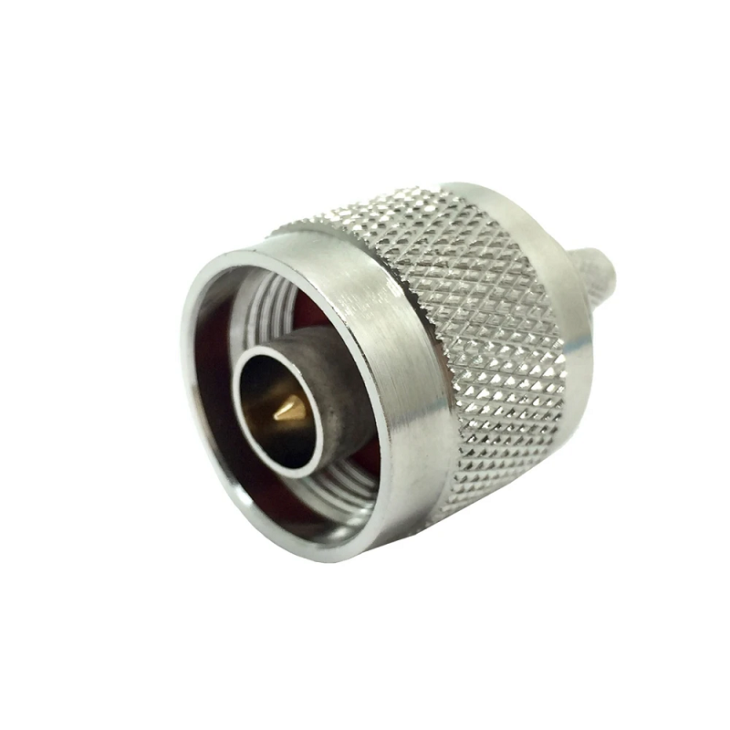
Engineered originally for heavy-duty radio systems, the coax n connector remains a workhorse for rugged, medium-to-high power installations. Its internal silicone o-ring seal yields excellent weather resistance, making the coax n connector ideal for outdoor RF infrastructure.
Operating Frequency: DC to 11 GHz (standard), up to 18 GHz (precision air-dielectric designs).
Impedance: Primary 50 Ω (75 Ω specialized variants exist).
Coupling Mechanism: 5/8-24 UNEF threaded interface.
Best Applications: Wireless base stations, cellular Distributed Antenna Systems (DAS), outdoor antennas, and microwave links.
Pros: Weatherproof construction, low VSWR, robust power capacity.
Cons: Larger footprint; requires proper torque (approx. 12 in-lbs) for optimal RF performance.
SMA is a compact, high-frequency threaded connector widely utilized across microwave and board-level designs.
Operating Frequency: DC to 18 GHz (standard), up to 26.5 GHz (precision grade).
Impedance: 50 Ω.
Coupling Mechanism: 1/4-36 UNF threaded coupling.
Best Applications: Microwave modules, PCB edge launchers, IoT radios, Wi-Fi antennas.
Pros: Very small form factor with superior high-frequency performance.
Cons: Thin outer shell; limited mating cycle life (~500 cycles); low RF power capacity.
Designed as a threaded adaptation of the BNC architecture, the TNC solves high-vibration connection failures.
Operating Frequency: DC to 11 GHz (precision extended designs to 18 GHz).
Impedance: 50 Ω and 75 Ω options.
Coupling Mechanism: 7/16-28 UNEF threaded coupling.
Best Applications: Aerospace avionics, military ground vehicles, tactical communications, and railway systems.
Pros: Excellent shock and vibration resistance; weatherproof variants available.
Cons: Slower connect/disconnect cycle compared to BNC.
MCX connectors reduce space requirements by nearly 30% compared to SMB connectors while retaining identical inner pin dimensions.
Operating Frequency: DC to 6 GHz.
Impedance: 50 Ω and 75 Ω options.
Coupling Mechanism: Snap-on friction fit.
Best Applications: GPS receiver boards, cellular modules, telecommunications switching, and IoT enclosures.
Pros: Extremely compact; fast snap-on assembly without tools.
Cons: Low power handling; lower mechanical retention force.
MMCX is an ultra-small surface-mount connector engineered for dense electronic assemblies where space is extremely constrained.
Operating Frequency: DC to 6 GHz.
Impedance: 50 Ω.
Coupling Mechanism: Snap-on with full 360-degree free rotation capability.
Best Applications: Wi-Fi/Bluetooth PCBA modules, handheld radios, ultra-compact sensors.
Pros: Minimal PCB footprint; rotating joint prevents cable twist stress.
Cons: Delicate structure; low insertion/extraction force thresholds.
Named after its metric contact dimensions (7 mm inner pin, 16 mm outer conductor), the 7/16 DIN is built for high-power broadcast transmission and cellular infrastructure.
Operating Frequency: DC to 7.5 GHz.
Impedance: 50 Ω.
Coupling Mechanism: Heavy-duty M29 x 1.5 threaded coupling nut.
Best Applications: Cellular macro site antennas, multi-carrier base stations, FM broadcast transmitters.
Pros: Outstanding RF power handling; superior Passive Intermodulation (PIM) suppression.
Cons: Very heavy, bulky, and requires high torque values during installation.
| Interface Standard | Outer Diameter | Max Frequency | Power Rating | Mating Mechanism | Relative Cost |
| BNC | ~14.5 mm | 4 GHz | Medium | Bayonet Lock | Low (1.0x) |
| Type N | ~20.5 mm | 18 GHz | High | Threaded (5/8-24) | Moderate (1.5x) |
| SMA | ~6.4 mm | 18 - 26.5 GHz | Low to Medium | Threaded (1/4-36) | Moderate (1.3x) |
| TNC | ~15.5 mm | 11 - 18 GHz | Medium | Threaded (7/16-28) | Moderate (1.6x) |
| MCX | ~4.5 mm | 6 GHz | Low | Snap-on | High (1.8x) |
| MMCX | ~3.5 mm | 6 GHz | Low | Snap-on | High (2.0x) |
| 7/16 DIN | ~27.0 mm | 7.5 GHz | Very High | Threaded (M29) | Premium (3.0x) |
Selecting the ideal coaxial connector type involves matching electrical needs with mechanical constraints:
Operating Bandwidth: Ensure the connector's upper frequency cutoff comfortably exceeds the highest harmonic of the carrier signal. For millimeter-wave or high Ku/K-band applications, select SMA or higher precision connectors.
Power Requirements: Continuous wave (CW) power creates heat within center conductors. High RF power needs thick center pins found in 7/16 DIN or the coax n connector.
Environmental Exposure: Outdoor, marine, or tower deployments require waterproof gasket seals.
Vibration and Mechanical Stress: Avoid push-pull or bayonet designs (BNC) in high-vibration settings like aviation or rail transit. Threaded couplers (TNC, SMA, Type N) maintain continuous electrical contact without microphonics.
Physical Envelope: Dense RF boards or small enclosures demand MCX or MMCX snap-on interfaces to preserve board area.
Specifying an RF connector involves more than interface dimensions; long-term performance relies heavily on manufacturing tolerances, plating quality, and assembly standards. Sub-par machining can cause impedance discontinuities, high VSWR, and severe signal reflection.
Precision CNC machining of brass or stainless steel bodies ensures reliable mating dimensions across high-volume production batches. Gold-plated center pins reduce contact resistance and prevent oxidation over extended deployment lifecycles.
Engineers and procurement teams often partner with established RF manufacturing specialists like Worldpeak (Zhenjiang Worldpeak Communication Co., Ltd.) to streamline component sourcing. Manufacturing capabilities across all seven major connector families—including customized coax n connector configurations, specialized cable jumper assemblies, and low-PIM designs—ensure consistent performance for telecommunications, test instrumentation, and industrial RF infrastructure. Selecting a supplier with strict quality controls and direct factory supply chain support helps guarantee reliable RF signal integrity in any environment.

2026/09/25
Customize an rf high frequency cable for temperature, moisture, corrosion, vibration, flexing, and OEM validation needs.

2026/09/25
Streamline RF equipment assembly lines with custom coaxial jumpers. Reduce line-side rework, ensure precise routing, and boost production efficiency.

2026/09/25
Learn PL-259 connector selection, soldering, weatherproofing, and RF applications for dependable antenna feedlines.

2026/09/25
Confirm impedance for a 90 degree coax connector with an ODM test plan covering VNA setup, VSWR, acceptance criteria, and release records.

2026/09/25
Learn when an n type coax connector can omit extra anti-corrosion treatment and when OEM exposure conditions require it.

2026/09/25
Learn how the custom cable and wire sample process helps ODM buyers validate design, testing, and production readiness.