 EN
EN

What environmental resistance can be customized for OEM rf cable
2026/09/25
Customize an rf high frequency cable for temperature, moisture, corrosion, vibration, flexing, and OEM validation needs.
2026/09/08
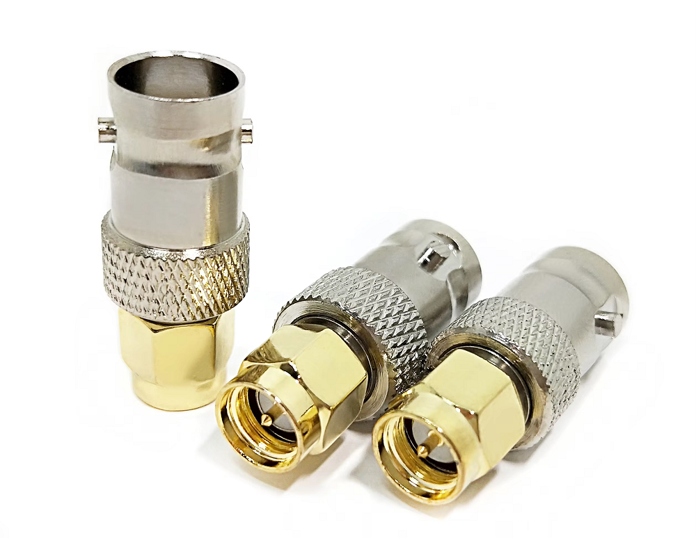
Reconfiguring wireless gear, extending antenna lines, or repositioning equipment racks often requires extending transmission paths beyond their original layout limits. In both commercial telecom networks and benchtop testing setups, completing a clean coaxial extension becomes necessary when equipment locations shift. Connecting separate cable assemblies with a high-quality coaxial cord adapter provides a flexible, cost-effective way to extend transmission lines without building brand-new cable assemblies from scratch.
However, joining transmission lines introduces impedance boundaries and potential insertion loss. Choosing an improper female to female coaxial adapter or daisy-chaining cheap barrel connector components can introduce unexpected signal loss, elevate VSWR, and ruin receiver sensitivity. Understanding how to manage RF signal extension setups ensures optimal performance across broadcast, cellular, and testing applications.
Technicians generally choose between two primary coaxial extension strategies: using a high-precision barrel connector joiner or replacing the entire run with a single continuous coaxial assembly.
Every joint placed into an RF signal extension path introduces a subtle impedance discontinuity. Calculating the total path loss of a coaxial extension run involves summing cable line attenuation with the insertion loss of each inline junction.
A well-engineered female to female coaxial adapter featuring gold-plated pin contacts typically adds only 0.1 dB to 0.3 dB of insertion loss at lower frequencies. Conversely, a poorly machined barrel connector with improper pin tension can introduce 0.5 dB or more of attenuation alongside high return loss reflections.
Consider a real-world calculation involving a 50-foot LMR-400 cable run operating at 900 MHz. Adding a secondary 50-foot LMR-400 section using a female to female coaxial adapter introduces roughly 3.9 dB of extra cable loss plus 0.2 dB of coupler insertion loss, bringing total added path loss to 4.1 dB. Knowing these numbers helps ensure overall system power levels remain safely above minimum receiver sensitivity limits.
Matching a coaxial cord adapter to specific system impedance and frequency requirements prevents severe power reflection and signal distortion.
| Adapter Type / Interface | Frequency Limit | Characteristic Impedance | Typical Insertion Loss | Common Application |
|---|---|---|---|---|
| BNC Barrel Connector | DC – 4 GHz | 50 Ohm / 75 Ohm | 0.1 – 0.2 dB | Lab Test Equipment / CCTV |
| SMA Female to Female Coaxial Adapter | DC – 18 GHz | 50 Ohm | 0.15 – 0.3 dB | High-Frequency Wi-Fi / Microwave |
| N-Type Coaxial Cord Adapter | DC – 11 GHz | 50 Ohm | 0.1 – 0.2 dB | Telecom Feeder / Outdoor Antenna |
| F-Type Coaxial Extension Coupler | DC – 3 GHz | 75 Ohm | 0.2 – 0.4 dB | CATV / Satellite Receiver |
| TNC Barrel Connector | DC – 11 GHz | 50 Ohm | 0.15 – 0.25 dB | High-Vibration Aerospace / Mobile |
Practical field deployments highlight when utilizing a coaxial cord adapter provides an efficient solution:
Following key assembly guidelines helps maintain signal stability across any coaxial extension project:
Maintaining low insertion loss across any coaxial extension setup requires high-precision machining tolerances and strict quality control. Inconsistent pin diameters or loose internal ground springs inside a low-grade barrel connector can cause signal dropouts and phase instability.
Specialized coaxial equipment manufacturers like WORLDPEAK support global telecommunications, broadcast, and industrial testing operations with a broad range of precision-machined coaxial cord adapter solutions. Offering female to female coaxial adapter products across BNC, N-type, SMA, TNC, and F-type configurations, WORLDPEAK utilizes advanced CNC machining, corrosion-resistant plating, and complete vector network analyzer testing infrastructure. Adhering to strict international quality standards, WORLDPEAK delivers durable, 100% factory-tested coaxial interconnect products to engineers and field technicians worldwide.

2026/09/25
Customize an rf high frequency cable for temperature, moisture, corrosion, vibration, flexing, and OEM validation needs.

2026/09/25
Streamline RF equipment assembly lines with custom coaxial jumpers. Reduce line-side rework, ensure precise routing, and boost production efficiency.

2026/09/25
Learn PL-259 connector selection, soldering, weatherproofing, and RF applications for dependable antenna feedlines.

2026/09/25
Confirm impedance for a 90 degree coax connector with an ODM test plan covering VNA setup, VSWR, acceptance criteria, and release records.

2026/09/25
Learn when an n type coax connector can omit extra anti-corrosion treatment and when OEM exposure conditions require it.

2026/09/25
Learn how the custom cable and wire sample process helps ODM buyers validate design, testing, and production readiness.