 EN
EN

7/16 DIN Connector Guide: High-Power RF Standard
2026/09/24
Choose a 7 16 connector for high-power RF: compare DIN and Type N, protect PIM margin, and apply field installation checks.
2026/09/02
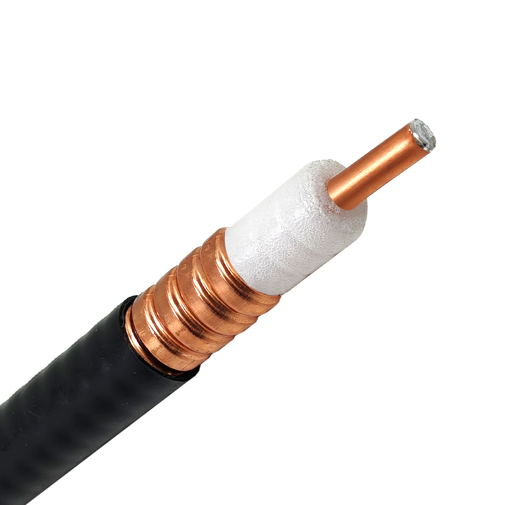
In modern cellular networks, the coaxial feeder is the primary arterial line linking base station transceiver equipment to the tower‑top antenna. While Remote Radio Head (RRH) architectures and Fiber‑to‑the‑Antenna (FTTA) systems continue to expand, high‑performance RF feeder cable systems remain essential for macro cell sites, small cell networks, and broadcast infrastructure worldwide. The quality, shielding, and installation accuracy of every coaxial feeder run directly dictate coverage radius, data throughput, link budget efficiency, and call drop rates.
Selecting the right cellular antenna cable and bulk coaxial cable for large‑scale buildouts requires a clear understanding of attenuation budgets, Passive Intermodulation (PIM) mitigation, and thermal durability.
Selecting an appropriate base station feeder comes down to balancing physical cable flexibility against Signal Attenuation (dB loss per 100 meters) at operating frequencies such as 900 MHz, 1800 MHz, or 3.5 GHz 5G bands.
| Cable Type | Outer Diameter | Attenuation at 900 MHz | Attenuation at 1800 MHz | Max Power (at 900 MHz) | Primary Site Application |
|---|---|---|---|---|---|
| 1/4 inch | 7.2 mm | 11.2 dB/100m | 16.8 dB/100m | 0.5 kW | Cabinet jumpers, indoor DAS |
| 3/8 inch | 9.5 mm | 8.5 dB/100m | 12.5 dB/100m | 0.8 kW | In‑building distribution runs |
| 1/2 inch | 12.7 mm | 6.5 dB/100m | 9.8 dB/100m | 1.2 kW | Short tower jumpers, small cell feeders |
| 7/8 inch | 22.2 mm | 3.9 dB/100m | 5.8 dB/100m | 2.5 kW | Standard macro cell main runs |
| 1‑1/4 inch | 31.8 mm | 2.7 dB/100m | 4.0 dB/100m | 4.0 kW | Long macro feeder runs |
| 1‑5/8 inch | 41.3 mm | 2.0 dB/100m | 3.0 dB/100m | 6.0 kW | High‑power broadcast, long trunk lines |
Standard braided cables fall short in exposed tower environments. Permanent macro cell installations depend on corrugated copper RF feeder cable variants designed to resist moisture, UV damage, and mechanical deformation.
Determining the right coaxial feeder gauge starts with calculating the site's allowable loss budget. A fraction of a decibel saved along the transmission path translates to significantly broader cell edge coverage and higher uplink data rates.
Consider a macro cell tower deployment with a 50‑meter vertical run and a 5‑meter horizontal path into the shelter, totaling 55 meters of base station feeder routing:
Loss Budget (7/8 inch) = 55m × (3.9 dB / 100m) = 2.15 dB at 900 MHz
Loss Budget (1/2 inch) = 55m × (6.5 dB / 100m) = 3.58 dB at 900 MHz
Choosing a 7/8‑inch coaxial feeder over a 1/2‑inch cable saves 1.43 dB of signal power. Across a multi‑year network lifecycle, this power retention improves link reliability, extends receiver sensitivity, and minimizes base station amplifier power demands.
Passive Intermodulation (PIM) occurs when non‑linear junctions in the RF path generate unwanted signals that leak into adjacent receive channels. Modern multi‑carrier LTE and 5G networks demand low‑PIM ratings (typically ≤‑160 dBc) across all RF feeder cable connections to maintain network capacity.
Key factors for controlling PIM on base station sites include:
For regional network rollouts, emergency maintenance fleets, and system integrators, procuring bulk coaxial cable directly yields operational and logistical advantages:
Proper mechanical installation safeguards the integrity of the coaxial feeder against severe weather, lightning strikes, and physical tension.
Grounding kits must be installed at critical points along the RF path to divert lightning strikes and dissipate static build‑up safely to the grounding grid:
Every outdoor coaxial feeder connection requires a multi‑layer protective barrier:
Designing and deploying resilient cellular infrastructure requires robust components engineered to withstand demanding outdoor environments. Worldpeak delivers an extensive portfolio of RF feeder cable solutions, premium connectors, and accessories engineered for global telecom deployments.
By prioritizing tight manufacturing tolerances, low‑PIM construction, and reliable bulk coaxial cable distribution, Worldpeak supports network operators and turnkey contractors with scalable RF connectivity solutions worldwide.

2026/09/24
Choose a 7 16 connector for high-power RF: compare DIN and Type N, protect PIM margin, and apply field installation checks.

2026/09/24
Compare TNC connector types, specs and applications, including RP-TNC, bulkhead options, vibration performance and adapter selection.

2026/09/24
Understand MMCX connector basics, RF limits, and how to choose the right coaxial interface for compact systems.

2026/09/24
Understand RP-SMA connector polarity, mating rules, frequency checks, and OEM termination options for reliable RF builds.

2026/09/24
Choose the right bnc male connector for RF, CCTV and test systems with clear 50Ω vs 75Ω, type and installation guidance.

2026/09/24
Compare LMR400 specs, cable loss, uses, connectors and RG8/RG213 alternatives with a practical RF loss-budget method.