 EN
EN

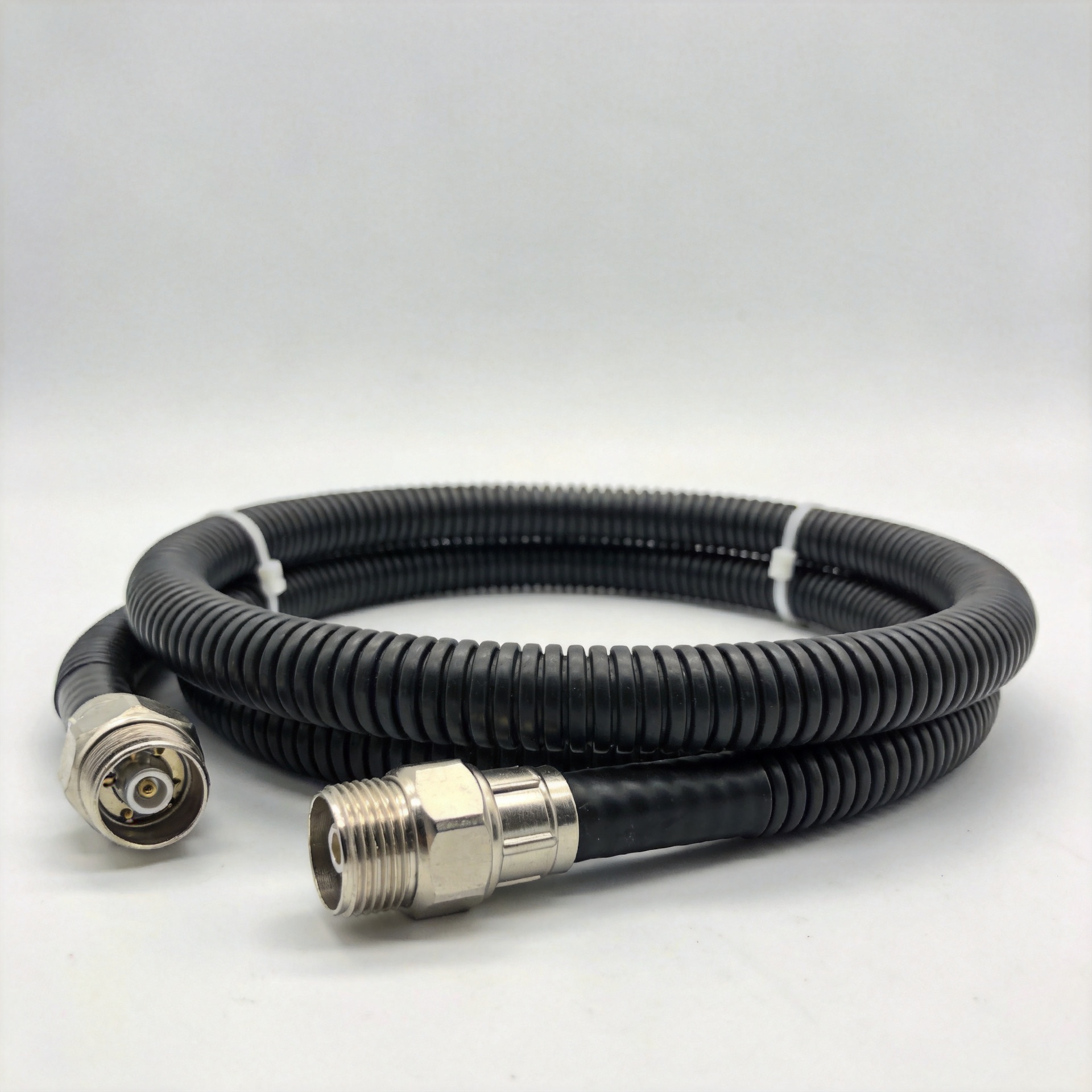
Feeder Cable Assembly Raw Wire: Buyer's Guide and Specifications
Selecting the right feeder cable assembly raw wire is one of those procurement decisions that looks routine on a spec sheet but quietly determines whether your base station, antenna run, or indoor distribution system meets its designed link budget—or falls short. The wrong cable size, connector interface, or weatherproofing specification creates problems that surface months into service, well after the original procurement window has closed.
This guide covers the key selection criteria as a practical checklist for engineers and procurement teams evaluating feeder cable assembly raw wire for telecom, broadcast, and antenna infrastructure applications.
What Is RF Feeder Cable Assembly Raw Wire?
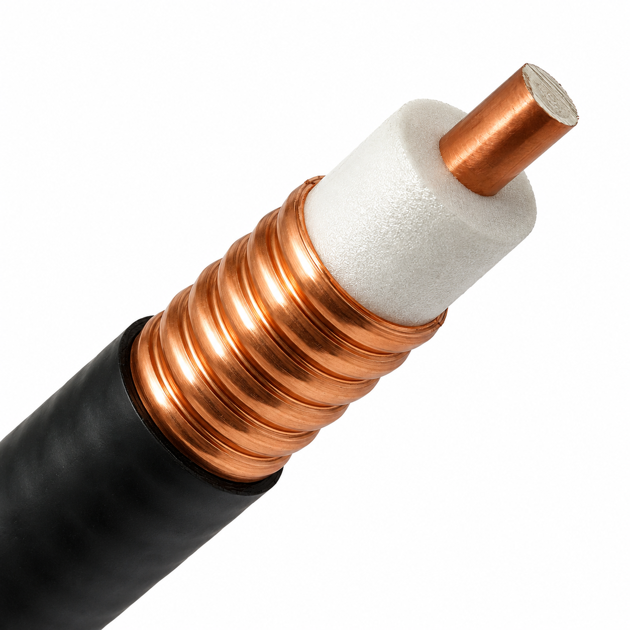
In RF and telecom contexts, feeder cable assembly raw wire refers to the coaxial transmission line that carries signal between a base station transceiver, antenna port, or distributed antenna system (DAS) node and the antenna element—including the terminated connector assembly at each end. Unlike small-diameter coaxial cables used for bench connections, feeder cables are designed for high power handling, low insertion loss over long runs, and outdoor durability. The "raw wire" component refers to the bulk cable stock before termination: the corrugated copper outer conductor, foam or air dielectric, and inner conductor that define the cable's electrical performance.
This category differs from lower-power connector interfaces such as BNC wire assemblies used in CCTV or test equipment, or signal conversion adapters like BNC to RJ45 used in AV distribution. RF feeder cables operate at significantly higher power levels and are built to maintain 50-ohm characteristic impedance across the target frequency range of the system.
Buyer's Checklist: 7 Criteria Before You Specify
1. Impedance and Frequency Range
The first item on any feeder cable assembly raw wire order is characteristic impedance. For telecom base station and antenna applications—4G LTE, 5G NR, and DAS infrastructure—the standard is 50 ohms. Beyond impedance, verify that the cable's upper frequency rating covers the system's highest operating frequency with adequate margin. A cable rated to 3 GHz may show elevated VSWR when pushed toward 5G FR1 frequencies without derating.
2. Cable Size and Insertion Loss Trade-Off
Cable size is the primary control for insertion loss on long feeder runs. Before choosing between 1/2-inch, 7/8-inch, and 1-5/8-inch options, consider: how many meters does this feeder run cover, and what is the maximum acceptable loss budget from transceiver to antenna port?
Doubling the cable diameter approximately halves the skin-effect resistance and, with it, insertion loss per unit length at a given frequency. As a reference, 1/2-inch corrugated copper feeder cable achieves approximately 1.90 dB per 100 feet at 750 MHz, while 7/8-inch cable achieves approximately 0.98 dB per 100 feet at the same frequency—roughly half the loss at double the diameter. For macro base stations with 30-meter or longer feeder runs, the 7/8-inch specification is generally the minimum acceptable size before system gain margin comes under pressure. The 7/8\" Corrugated Copper Feeder Cable - 50 Ohm from Worldpeak represents this class of cable for base station and broadcast antenna applications.
The 1-5/8-inch size suits macro base station trunk feeders and broadcast transmission lines where power handling and minimum loss take priority.
3. Connector Interface: N-Type, 7/16 DIN, and Interface Matching
The connector interface at each end of the feeder cable assembly sets both the electrical performance ceiling and the mechanical reliability of the connection. For base station feeder runs, the standard interfaces are N male connector for lower-power links and 7/16 DIN for higher-power transmission lines. N-type male connectors are the common choice in the 0–3 GHz range, with consistent contact geometry and reliable weatherproofing when properly torqued and sealed.
A recurring procurement error is specifying the connector type without specifying gender, which leads to mismatch on arrival. Each order for a feeder cable assembly should state connector type, gender, and gender at each end—for example, "N male to N male, 7/8-inch feeder cable."
4. Pre-Terminated vs. Raw Wire: Installation Flexibility
For contractors needing rapid deployment with less on-site termination labor, pre-terminated feeder cable assemblies offer a clear practical advantage: each connector is factory-installed, electrically tested, and ready to install without field crimp or solder work. The Worldpeak 1-2 feeder Pre-Terminated Cable Assembly is an example—a factory-terminated assembly that reduces field installation variables and supports incoming inspection at the project site.
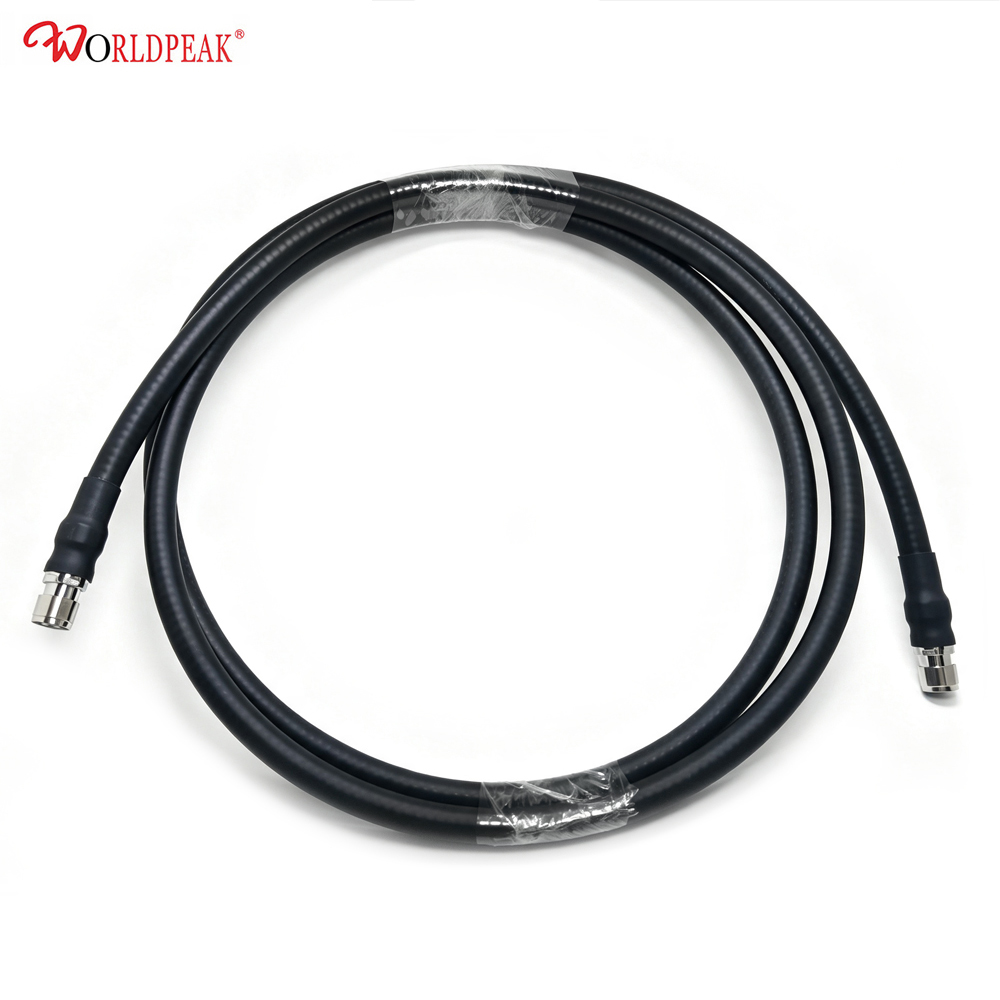
Raw wire stock fits situations where exact cable lengths are not known at order time, where installation routes through conduit before termination, or where an in-house assembly process ensures controlled quality. Either approach requires connector torque compliance and weatherproofing at the installed interface.
5. Power Handling Capacity
Power handling depends on both cable type and connector interface. Larger cables and 7/16 DIN connectors accommodate higher continuous and peak power than smaller options. Where power is the binding constraint—broadcast or high-power DAS systems, for instance—validate cable and connector selection against peak envelope power, not just average power. Under-specifying power handling is a common contributor to connector body heating and feeder degradation in high-power installations.
6. Outdoor Environmental Rating and Weatherproofing
My procurement approach for outdoor feeder cable assemblies was originally focused on electrical specifications. A post-installation review changed that: moisture ingress at a connector interface that had passed incoming inspection traced back to weatherproofing tape application inconsistency across installation crews. Outdoor-rated feeder cable assemblies with integrated weatherproofing at the connector interface are more reliable than assemblies depending entirely on field tape application.
If the installation environment stays within the cable's rated temperature and humidity range, the assembly will perform to spec. When either condition is regularly exceeded—high temperatures on a rooftop run, or sustained humidity in a tropical climate—the rated service life shortens. Confirm that the outer jacket compound is UV-stabilized for rooftop and tower installations, and that connector sealing is compatible with the site's environmental classification.
7. Custom Lengths and Non-Standard Configurations
DAS installations, rooftop multi-sector arrays, and high-rise building deployments frequently call for non-standard lengths to avoid excess cable coiling and keep signal path geometry clean. Custom feeder cable assembly fabrication—covering non-standard lengths, mixed-connector configurations, and application-specific jacket specifications—lets system integrators source precisely matched assemblies rather than adapting standard product to routing constraints that catalog lengths don't address.
Matching Cable Size to Application: Quick Reference
| Cable Size | Typical Application | Relative Loss | Installation Difficulty |
|---|---|---|---|
| 1/2 inch (12.7 mm) | Short base station jumpers, indoor DAS | Higher (approx. 1.90 dB/100ft @ 750 MHz) | Easier—more flexible, lighter |
| 7/8 inch (22.2 mm) | Base station tower feeders, outdoor antenna runs | Medium (approx. 0.98 dB/100ft @ 750 MHz) | Moderate—requires proper hangers and bend radius management |
| 1-5/8 inch (41.3 mm) | Macro base station trunk lines, broadcast transmitters | Lower (approx. 0.50 dB/100ft @ 750 MHz) | More demanding—rigid, heavy, requires tower crew support |
Working With a Qualified Supplier
The selection criteria above compound when applied across a multi-site procurement. A supplier focused exclusively on RF connectors, coaxial cable assemblies, and RF passive components can provide application-specific guidance that general-line distributors typically cannot. Pre-shipment electrical testing—insertion loss and VSWR sweep on each assembly—combined with custom specification capability, reduces procurement risk at both incoming inspection and system commissioning.
Summary
Specifying feeder cable assembly raw wire for telecom and antenna infrastructure starts with 50-ohm characteristic impedance, cable size matched to the insertion loss budget, and connector interface suited to the power level and frequency range. Pre-terminated assemblies reduce field installation variables; custom lengths address DAS and complex routing requirements. Weatherproofing at the connector interface—not just the cable jacket—is what determines long-term reliability at tower and rooftop installations. Verify these criteria against the system design before the RFQ goes out.





