 EN
EN

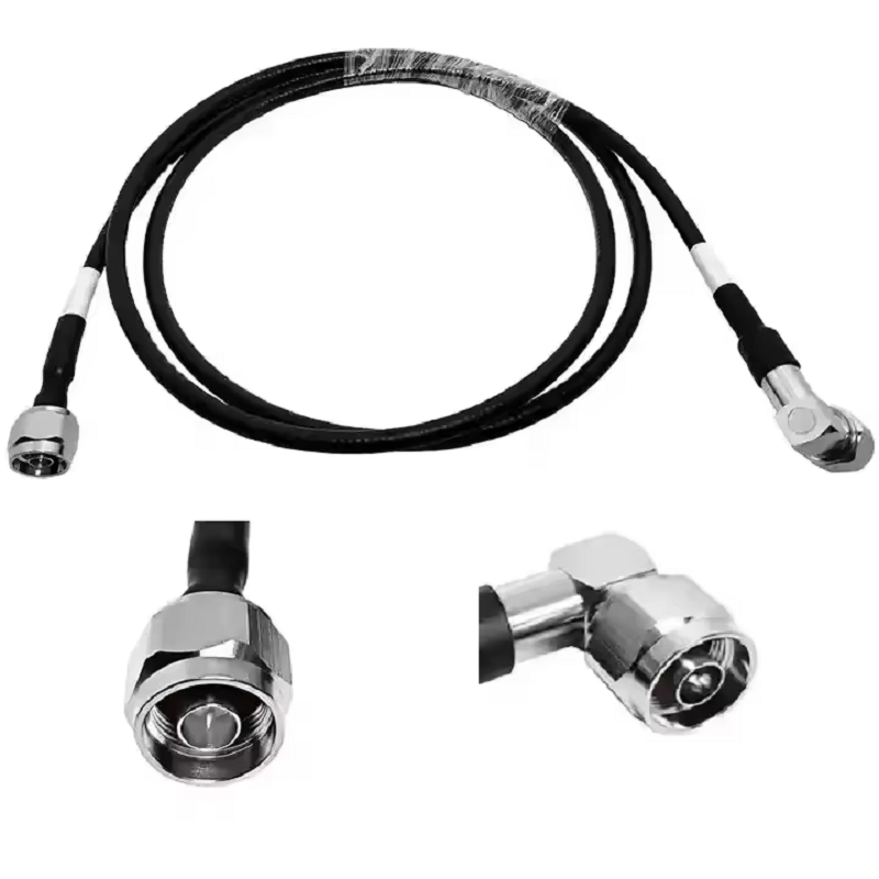
In cellular tower infrastructure, distributed antenna systems, and base transceiver stations, a feeder cable functions as the central circulatory system for high-frequency RF power. Transmitting signals between radio transceivers and masthead antennas requires uncompromising continuity. When a contractor specifies a transmission line purely on purchase price or catalog availability, the entire link budget suffers. Every fraction of a decibel dropped across a long vertical run subtracts directly from receiver sensitivity and transmitter reach.
Electrical Roles and Attenuation Trade-offs in RF Transmission
A primary feeder cable carries high-power RF energy across heights exceeding several hundred feet while isolating the signal path from external interference. Modern cellular base stations operate in dense multi-carrier environments where passive intermodulation and signal leakage degrade data throughput. Solid outer conductor corrugated copper cables maintain shielding effectiveness exceeding 120 dB, preventing crosstalk across co-located cellular bands.
Attenuation represents the dominant electrical constraint. Because skin effect losses increase proportionally with the square root of frequency, larger diameter conductors are essential for mid-band 5G and LTE spectrum. A well-designed feeder cable maintains strict 50-ohm characteristic impedance throughout the operational band.
Feeder Cable Dimension
Outer Conductor Construction
Attenuation @ 900 MHz (per 100 ft)
Attenuation @ 2100 MHz (per 100 ft)
Minimum Bend Radius
Typical Cellular BTS Application
1/2 Inch Standard
Corrugated Copper Tube
~2.1 dB
~3.3 dB
125 mm (5.0 in)
Rooftop jumpers, short antenna drops, DAS riser runs
7/8 Inch Standard
Corrugated Copper Tube
~1.1 dB
~1.8 dB
250 mm (10.0 in)
Primary tower vertical runs, mid-distance base station trunks
1-1/4 Inch Standard
Corrugated Copper Tube
~0.8 dB
~1.3 dB
380 mm (15.0 in)
High-power macro sites, long horizontal transmission paths
1-5/8 Inch Standard
Corrugated Copper Tube
~0.6 dB
~1.1 dB
500 mm (20.0 in)
High-elevation broadcast towers, ultra-long cellular trunks
| Feeder Cable Dimension | Outer Conductor Construction | Attenuation @ 900 MHz (per 100 ft) | Attenuation @ 2100 MHz (per 100 ft) | Minimum Bend Radius | Typical Cellular BTS Application |
|---|---|---|---|---|---|
| 1/2 Inch Standard | Corrugated Copper Tube | ~2.1 dB | ~3.3 dB | 125 mm (5.0 in) | Rooftop jumpers, short antenna drops, DAS riser runs |
| 7/8 Inch Standard | Corrugated Copper Tube | ~1.1 dB | ~1.8 dB | 250 mm (10.0 in) | Primary tower vertical runs, mid-distance base station trunks |
| 1-1/4 Inch Standard | Corrugated Copper Tube | ~0.8 dB | ~1.3 dB | 380 mm (15.0 in) | High-power macro sites, long horizontal transmission paths |
| 1-5/8 Inch Standard | Corrugated Copper Tube | ~0.6 dB | ~1.1 dB | 500 mm (20.0 in) | High-elevation broadcast towers, ultra-long cellular trunks |
Sizing Decisions and Physical Tower Route Dynamics
Selecting a large trunk feeder cable solves attenuation challenges on paper, but physical site mechanics dictate practical limits. A 1-5/8 inch corrugated line delivers exceptional conductivity, yet its weight and wind sail area demand reinforced structural brackets, calibrated hoisting grips, and substantial cable tray space.
During tower installation, rigging crews must secure the feeder cable using calibrated stainless-steel hangers spaced every three to four feet along vertical ladders. Failure to support the run properly invites metal fatigue under heavy wind flutter or winter icing conditions. For transitions around cable bridge bends and cabinet entries, engineers often transition from a stiff 7/8 inch feeder cable to a 1/2 inch superflexible jumper. This hybrid topology prevents mechanical leverage from cracking ceramic seals inside radio chassis connectors.
Impedance Matching and Misconceptions Around Utility Coaxial Lines
A common procurement mistake on commercial installations stems from misunderstanding characteristic impedance. Broadcast distribution, satellite television downlinks, and building security feeds rely on 75-ohm lines such as standard rg6 coax cable. In contrast, commercial telecom radios and cellular base stations operate exclusively across 50-ohm transmission systems.
Installing an rg6 coax cable into a 50-ohm cellular transmitter creates an immediate 1.5:1 baseline VSWR mismatch. This structural discontinuity reflects roughly 4% of forward power back into the output stage of the power amplifier, creating thermal buildup and degrading modulation accuracy. Furthermore, an rg6 cable features aluminum foil shielding and a copper-clad steel center conductor designed for low mechanical pull strength and high-frequency television frequencies, not the continuous high-power handling required by a cellular feeder cable.
Transmission Cable Family
Characteristic Impedance
Center Conductor Material
Shielding Topology
Primary Engineering Purpose
Corrugated BTS Feeder
50 Ohm
Solid Copper / Copper Clad Aluminum
Continuous Corrugated Copper Tube
Macro cell towers, BTS transmitters, high-power RF trunks
Superflexible RF Jumper
50 Ohm
Copper-Clad Aluminum or Solid Wire
Helical Corrugated Copper
Equipment tail runs, antenna connections, cabinet links
Broadband RG6 Coax Cable
75 Ohm
Copper-Clad Steel (CCS)
Aluminum Foil plus Braid
CATV, satellite receivers, baseband video distribution
Precision Mini-Coax
50 Ohm
Silver-Plated Copper
Silver-Plated Braid / Foil
Cabinet routing, test fixtures, indoor radio jumpers
| Transmission Cable Family | Characteristic Impedance | Center Conductor Material | Shielding Topology | Primary Engineering Purpose |
|---|---|---|---|---|
| Corrugated BTS Feeder | 50 Ohm | Solid Copper / Copper Clad Aluminum | Continuous Corrugated Copper Tube | Macro cell towers, BTS transmitters, high-power RF trunks |
| Superflexible RF Jumper | 50 Ohm | Copper-Clad Aluminum or Solid Wire | Helical Corrugated Copper | Equipment tail runs, antenna connections, cabinet links |
| Broadband RG6 Coax Cable | 75 Ohm | Copper-Clad Steel (CCS) | Aluminum Foil plus Braid | CATV, satellite receivers, baseband video distribution |
| Precision Mini-Coax | 50 Ohm | Silver-Plated Copper | Silver-Plated Braid / Foil | Cabinet routing, test fixtures, indoor radio jumpers |
While an rg6 cable provides cost-effective service across residential CATV drops, attempting to utilize an rg6 coax cable as an emergency patch inside a cellular BTS shelter ruins system return loss. Even if custom mechanical adapters are used to join the different interfaces, the inherent impedance clash produces recurring standing waves. Choosing an rg6 cable for cellular systems introduces unrecoverable insertion loss. Field technicians must store 75-ohm utility spools far from telecom staging areas to prevent accidental deployment of an rg6 cable in mission-critical wireless hardware.
Jumper Strategies and Interconnect Topologies
Terminal interconnections require flexible transmission lines that absorb vibration without inducing contact fatigue. While the main feeder cable handles the bulk vertical path, shorter jumper assemblies interface directly with sector antennas, remote radio heads, and test couplings.
In dense DAS enclosures, test racks, and low-power microcell nodes, a compact sma to sma cable is the standard configuration for modular interconnects. Specifying a double-shielded, low-loss sma to sma cable ensures clean transmission between bandpass filters, power splitters, and monitor ports. The threaded coupling nut of an sma to sma cable provides mechanical stability under chassis vibration, preventing microphonic noise spikes.
However, field crews must recognize interface boundaries. An sma to sma cable belongs inside sheltered cabinets, small-cell enclosures, and diagnostic test setups. Routing an sma to sma cable along an exposed tower face exposes its thin dielectric and fine threads to wind buffeting, water intrusion, and premature failure. High-power outdoor antenna jumpers require 4.3-10 or 7/16 DIN connectors mated to 1/2 inch flexible feeder cable sections to withstand multi-kilowatt peak RF power levels.
Weatherproofing, Grounding, and Environmental Sealing
Environmental exposure accounts for the overwhelming majority of transmission line failures. Water ingress into a foam-dielectric feeder cable turns the porous insulator into an attenuating sponge, triggering sudden link failure. Complete site reliability requires multi-layer weatherproofing and systematic lightning protection.
-
Weatherproofing connections at antenna and radio ports using a three-layer wrap of premium vinyl tape, butyl mastic sealant, and an outer UV-resistant vinyl overwrap, or pre-formed cold-shrink silicone sleeves.
-
Installing grounding kits at three mandatory points: near the antenna transition at the top of the tower, at the tower base prior to the horizontal ice bridge, and at the entry port bulkhead before entering the BTS shelter.
-
Maintaining smooth, continuous grounding leads oriented downward toward the master ground bus bar to provide a low-inductance path for lightning strikes.
-
Ensuring minimum cable bend radius limits are never violated during pulling, avoiding crimped jackets that degrade local impedance and invite water pooling.
Acceptance Testing and Long-Term Field Maintenance
Commissioning an RF transmission line requires documented baseline sweep measurements before declaring a base station operational. A visually neat feeder cable run can harbor internal structural damage caused by over-torqued hoist grips or sharp bend corners.
Field Test Parameter
Target Acceptance Metric
Diagnostic Purpose
Corrective Action If Failed
Return Loss (VSWR)
> 20 dB (VSWR < 1.22:1) across operational band
Verifies total impedance continuity and proper connector seating
Re-terminate suspect connectors or replace crushed jumper
Distance-to-Fault (DTF)
Clean profile with no localized reflection spikes
Pinpoints exact physical location of cable crimps, kinks, or water intrusion
Inspect physical route at identified footage; repair jacket or slice
Passive Intermodulation (PIM)
Better than -153 dBc (tested with 2 x 20W carriers)
Identifies microscopic metal debris, loose threads, or oxidized contacts
Clean connector mating faces with lint-free wipes; retorque to spec
DC Resistance / Continuity
Within 5% of manufacturer datasheet nominal
Confirms intact center conductor pin contact and ground continuity
Check center pin solder/crimp and verify ground kit clamp torque
| Field Test Parameter | Target Acceptance Metric | Diagnostic Purpose | Corrective Action If Failed |
|---|---|---|---|
| Return Loss (VSWR) | > 20 dB (VSWR < 1.22:1) across operational band | Verifies total impedance continuity and proper connector seating | Re-terminate suspect connectors or replace crushed jumper |
| Distance-to-Fault (DTF) | Clean profile with no localized reflection spikes | Pinpoints exact physical location of cable crimps, kinks, or water intrusion | Inspect physical route at identified footage; repair jacket or slice |
| Passive Intermodulation (PIM) | Better than -153 dBc (tested with 2 x 20W carriers) | Identifies microscopic metal debris, loose threads, or oxidized contacts | Clean connector mating faces with lint-free wipes; retorque to spec |
| DC Resistance / Continuity | Within 5% of manufacturer datasheet nominal | Confirms intact center conductor pin contact and ground continuity | Check center pin solder/crimp and verify ground kit clamp torque |
Technicians should store electronic copies of the baseline sweep profile in the BTS shelter documentation pouch. During future troubleshooting calls, running an updated DTF sweep against the original baseline quickly reveals whether the main feeder cable has sustained physical trauma, connector corrosion, or internal moisture degradation.
Engineering Capabilities and Manufacturing Partnership
Deploying durable wireless communications infrastructure requires dependable RF hardware manufactured to tight physical tolerances. WORLDPEAK produces a comprehensive portfolio of high-performance transmission lines, corrugated feeder cable assemblies, precision connectors, and custom interconnects engineered for macro cellular base stations, rooftop wireless installations, and industrial DAS networks.
With advanced automated cable extrusion lines, high-precision CNC connector machining centers, and comprehensive factory PIM and VNA testing suites, WORLDPEAK ensures every assembly delivers superior return loss and minimal attenuation. Supported by extensive manufacturing capacity, custom pre-terminated assembly capabilities, and responsive global supply chain logistics, WORLDPEAK delivers the durable connectivity solutions telecommunications operators and installation contractors count on for long-term network reliability.





