 EN
EN

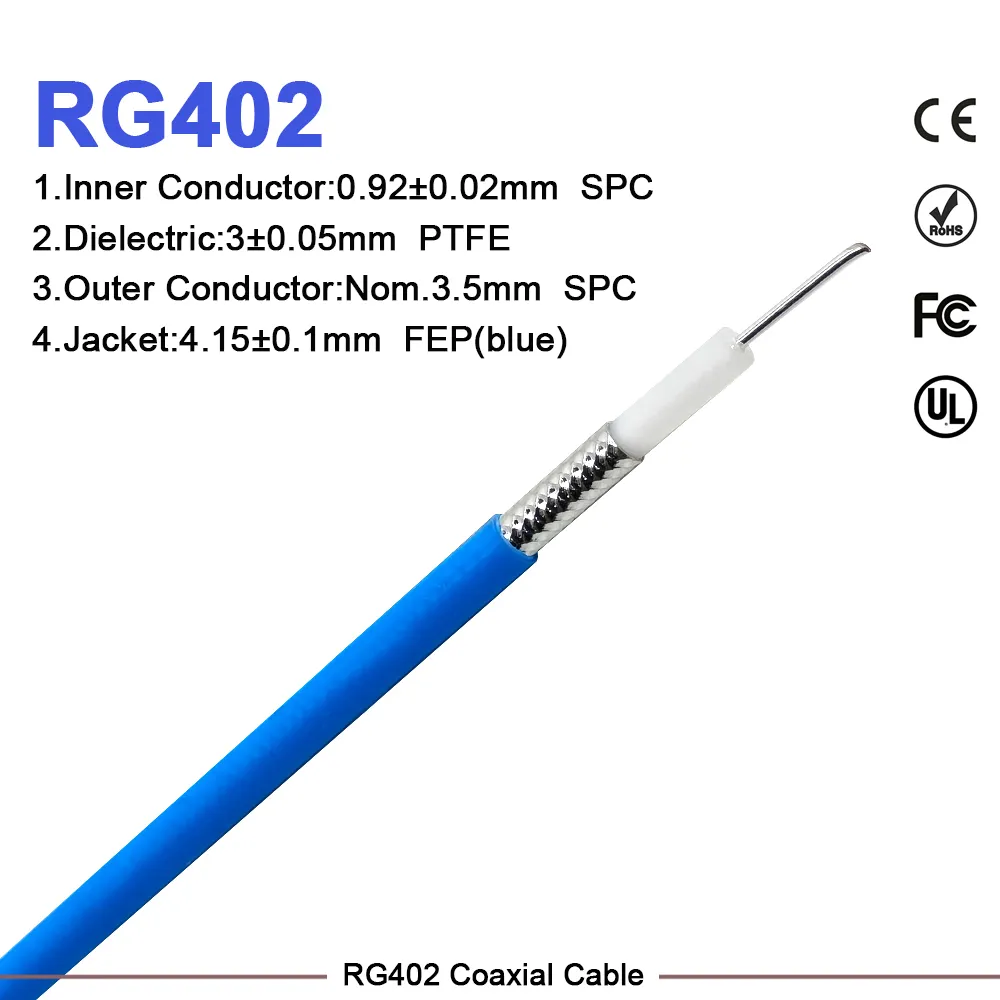
Flexible Coaxial Jumper: Bend Radius and Applications
As an RF systems engineer who has designed antenna feed systems for base stations and laboratory measurement setups, I've learned that the choice of a flexible coaxial jumper determines whether the entire signal chain performs to spec—or quietly degrades under routing constraints. The decision comes down to a question most buyers don't ask early enough: how tight does this cable need to bend, and at what frequency will it operate?
A flexible coaxial jumper connects antenna ports, base station equipment, and laboratory instruments where a rigid cable would crack or fail under the routing geometry. But flexibility and low loss pull in opposite directions. Before specifying flexible rf cables for any deployment, understanding what drives that trade-off saves both rework and link budget.
How Bend Radius Constrains a Flexible Coaxial Jumper
Every coaxial cable has a minimum bend radius. Exceed it and you introduce impedance discontinuities that raise VSWR, increase insertion loss, and eventually cause structural failure through repeated stress cycling.
Early in my experience with cable routing inside rack-mounted instruments, I optimized purely for insertion loss per meter. The blind spot was minimum bend radius, which set an independent constraint that the lowest-loss cable option couldn't overcome in a tightly packaged instrument chassis. That lesson changed how I approach every flexible coaxial jumper specification: bend radius and insertion loss must be evaluated together, not in sequence.
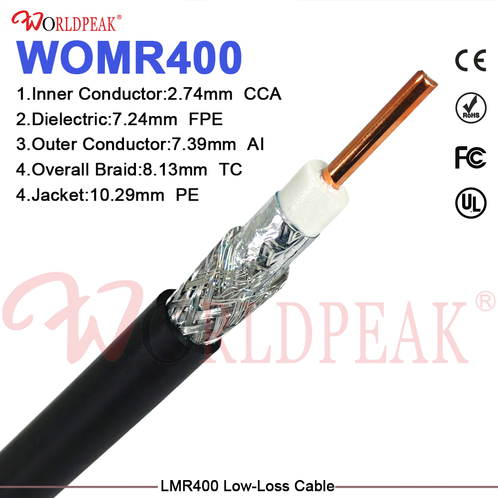
RG-58 (50 Ω, approximately 0.195" OD) has a minimum bend radius of roughly 1.5 inches, making it one of the most routing-friendly options for compact enclosures and laboratory patch panels. LMR-400 requires at least 4 inches of bend radius, which rules out many tight routing paths but delivers substantially lower loss per meter at frequencies above 1 GHz. RG8X occupies the middle ground: more flexible than LMR-400 with better insertion loss characteristics than RG-58, covering a wide range of base station and outdoor antenna applications where the cable must navigate some bends but runs longer than a bench patch cord.
Cable Type Comparison: RG58, RG8X, and LMR400
| Cable Type | Outer Diameter | Min. Bend Radius | Loss at 1 GHz (approx.) | Typical Applications |
|---|---|---|---|---|
| RG-58 | 0.195" | ~1.5 in (38 mm) | ~0.55 dB/m | Lab bench, short indoor runs under 6 m, low-power signal paths |
| RG8X | 0.242" | ~2.5 in (64 mm) | ~0.35 dB/m | Base station equipment rooms, medium outdoor runs, indoor feeder transitions |
| LMR-400 | 0.405" | ~4 in (100 mm) | ~0.13 dB/m | Tower feeder runs, high-power base station links, long outdoor cable paths |
If the installation environment stays below 60°C and the run is shorter than 6 meters, RG-58 or RG8X will perform within spec for most telecom and laboratory signal paths. Once the run length increases or the operating frequency rises above 2.4 GHz, loss accumulates enough to affect link budget, and LMR-400 becomes the better option—provided the routing geometry can accommodate the larger bend radius.
Before choosing, ask yourself: how many turns does the cable path require, and what is the tightest bend in the route? If the answer involves several 90-degree corners through a congested equipment bay, RG-58 or RG8X is the more practical choice. If the flexible coaxial jumper runs along a tower face for 15 to 20 meters with open routing, LMR-400's lower loss is worth specifying.
Application Scenarios for Flexible Coaxial Jumper Systems
Antenna Installations
At outdoor antenna installations, a flexible coaxial jumper bridges the antenna port and the surge protector or feeder transition point. Flexibility at this junction reduces mechanical stress on the antenna connector during wind-induced movement, while insertion loss at the operating frequency—typically 700 MHz to 3.5 GHz for cellular antennas—determines how much link margin is consumed before the signal reaches the tower base. Specifying the correct bend radius for the mounting geometry avoids outer conductor micro-cracking that causes intermittent signal loss after commissioning.
Base Station Equipment Rooms
Inside base station equipment rooms, flexible rf cables connect RF unit ports, filters, and combiners in dense rack configurations. Short jumper lengths of 0.3 to 1 meter dominate these runs; bend radius matters more than loss per meter in this scenario. RG8X is a common choice because it balances routing flexibility with insertion loss low enough for short intra-rack links. For installations requiring a pre-tested assembly with verified sweep performance, the Worldpeak 1-2 super flexible Pre-Terminated Cable Assembly eliminates the uncertainty of field-terminated connections in these compact spaces, with electrical data included in the shipment documentation for incoming inspection.
Laboratory and Test Systems
Laboratory test setups require repeated connector mating during calibration cycles and configuration changes. A flexible coaxial jumper used on a measurement bench undergoes far more physical movement than a field-installed feeder assembly. On the measurement bench, flex life—the number of bend cycles the cable sustains before the outer conductor develops a fatigue crack—becomes a selection criterion alongside insertion loss and bend radius. When the measurement chain includes a coaxial bandpass filter, the flexible coaxial jumper connecting the filter ports should be short enough to avoid introducing resonance artifacts near the filter passband edges, and free of mechanical stress at connector interfaces.
OEM Options and Customization Lead Times
Standard catalog flexible rf cables cover common connector combinations, but system integrators often need non-standard lengths, mixed interfaces, or specific jacket materials. For volume OEM procurement, custom assembly fabrication reduces BOM complexity and ensures consistency across production orders.
Custom flexible coaxial jumper fabrication includes non-standard lengths, mixed-connector configurations, and application-specific outer jacket materials for UV resistance or low-temperature flexibility. Small-batch prototype orders allow design engineers to verify fit and performance before committing to production quantities. The LMR400 Low-Loss 50 Ohm Coaxial Cable is a standard offering for procurement teams specifying low-loss feeder and backhaul cable runs, while the Worldpeak RG196 50-Ohm Coaxial Cable Engineering Data and Selection Guide provides engineering parameters for teams evaluating alternative cable constructions for demanding signal integrity requirements.
Installation, Bending, and Weatherproofing
Roughly speaking, a flexible coaxial jumper routed through a 90-degree turn adds 0.05 to 0.1 dB of additional reflected power compared to a straight run—an approximate figure, not a link budget number. The practical rule: maintain bends at twice the minimum bend radius or greater wherever routing geometry permits, and avoid kinks entirely.
- Bending technique: Use a cable radius guide or bending template when forming tight corners in LMR-400. Hand-forming without a radius guide frequently produces kinks that deform the outer conductor and create an impedance discontinuity at the bend point.
- Connector torque: Apply the specified torque for the connector interface—typically 1 N·m for SMA, 3 N·m for N-type, and for compact threaded types like the 10 32 coaxial connector, follow the manufacturer specification—using a calibrated torque wrench. Under-torqued connections develop elevated VSWR after thermal cycling.
- Weatherproofing: For outdoor antenna jumper connections, apply self-amalgamating tape from the cable jacket inward to the connector body, overlapping each wrap layer by at least 50%. In high-UV environments, add a UV-stable outer protective tape layer over the amalgamating tape.
- Moisture seal: Ensure the tape seals against the cable jacket at the antenna port interface, not just the connector threads—incomplete sealing at this junction is a common moisture ingress point that only manifests after the first wet season.
Choosing the Right Flexible Coaxial Jumper for Your Application
There is no single right answer for every scenario—the flexible coaxial jumper selection depends on routing geometry, operating frequency, power level, and acceptable insertion loss for your specific installation. If your primary constraint is tight routing through a congested equipment rack or instrument chassis, minimum bend radius should carry the most weight. If the flexible coaxial jumper runs a significant distance at frequencies above 1 GHz and the path is relatively open, the lower loss per meter of LMR-400 or a super-flexible 1/2-inch construction reduces total signal attenuation in the link budget.
For procurement teams sourcing flexible rf cables at volume, requesting per-assembly swept insertion loss and VSWR data from the supplier allows incoming inspection to confirm each assembly meets specification before system integration—eliminating the risk of discovering degraded performance during commissioning rather than at the receiving dock. Pre-shipment electrical testing and documented test data are a practical baseline expectation for any flexible coaxial jumper used in base station, antenna, or laboratory measurement applications.





