 EN
EN

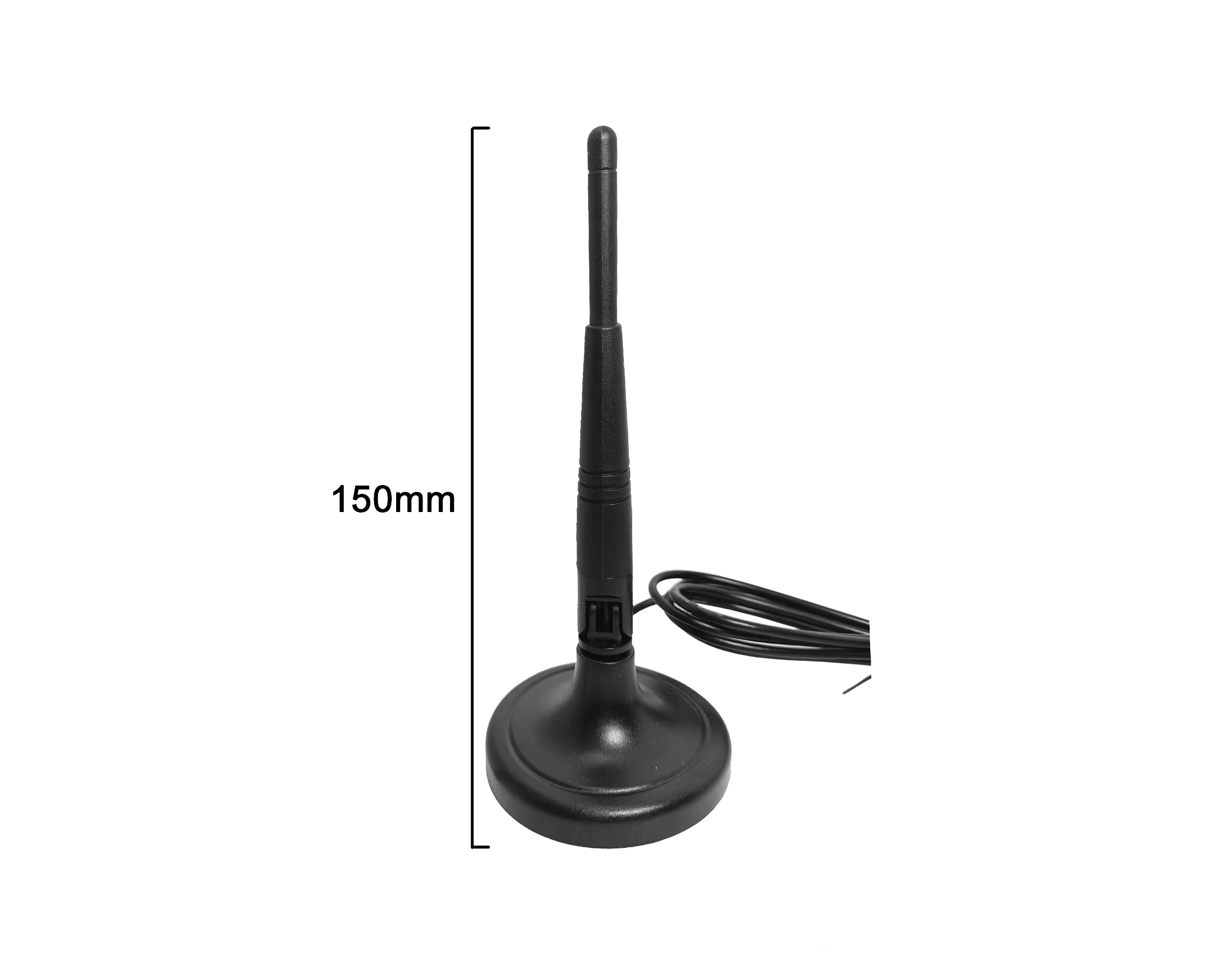
Achieving optimal signal reception or transmission within the 88–108 MHz Frequency Modulation (FM) band requires more than simply calculating the physical length of a half-wave radiator. A standard dipole fm antenna presents a symmetrical, balanced electrical structure with a nominal feedpoint impedance of 73 ohms in free space. Connecting this balanced antenna structure to an asymmetrical, unbalanced coaxial transmission line without proper impedance matching creates a severe electromagnetic boundary conflict.
This physical mismatch allows high-frequency currents to flow back down the outside shield of the coaxial cable, transforming the feed line into an active part of the radiator. This common integration oversight distorts the antenna radiation pattern, introduces severe electromagnetic interference into nearby electronics, and significantly degrades the signal-to-noise ratio.
To prevent shield radiation, system integrators must install a 1:1 voltage or current balun (balanced-to-unbalanced transformer) directly at the antenna feedpoint. This critical matching component isolates the coaxial ground from the balanced antenna arms, ensuring that the antenna cable connection functions purely as a low-loss signal transport channel rather than an uncontrolled radiative element.
Coaxial Feeder Loss Calculations and Attenuation Constants
Every coaxial feeder line introduces signal attenuation, transforming high-frequency electromagnetic energy into heat. While a miniature flexible line might simplify indoor routing behind an equipment rack, long outdoor transmission paths require robust, low-loss coaxial cables to prevent weak signals from dropping below the receiver threshold.
The High-Frequency Cable Attenuation Formula
The total attenuation (α) of a coaxial cable assembly at a specific frequency is determined by the physical resistive losses of the copper conductors (skin effect) and the dielectric absorption losses of the insulating medium. It can be expressed with the formula:
Total Attenuation (α) = (A * √f) + (B * f)
Where:
-
A represents the conductor loss coefficient.
-
B represents the dielectric loss coefficient.
-
f is the operating frequency in megahertz.
Conductor Loss: Skin effect restricts current flow to the outer skin of the center conductor at FM frequencies, increasing electrical resistance.
Dielectric Loss: High-purity foamed polyethylene or solid polytetrafluoroethylene (PTFE) dielectrics exhibit lower dissipation factors, minimizing dielectric absorption at 100 MHz.
Impedance Choice: While 50-ohm lines are the standard for high-power transmitters, 75-ohm coaxial lines offer the absolute minimum attenuation for low-power receiving systems, aligning closely with the natural 73-ohm impedance of a half-wave dipole FM antenna.
Dynamic Interface Demands in Complex Communications Sites
Modern communication towers and monitoring facilities often co-locate various wireless services, requiring clear distinction between adjacent cable runs. Mistaking a telemetry feed for a precision timing link is a costly installation error.
⚠️ ENGINEERING ALERT: Coaxial Cable Swapping
A precision gps antenna cable is engineered for high-frequency GPS signals (1575.42 MHz L1 band), typically featuring active low-noise amplifier bias paths and high-density double-shielding to block weak noise ingress. Substituting a high-loss, small-diameter gps antenna cable as a long feeder for an FM receiver results in severe signal attenuation. Conversely, routing high-frequency GPS signals through a lower-frequency bnc cable assembly leads to high insertion loss and signal degradation.
-
Dipole FM Antenna Feed: Operates at 88–108 MHz; benefits from 75-ohm or 50-ohm low-loss cabling; utilizes N-type, TNC, or BNC interfaces.
-
GPS Antenna Feed: Operates at 1.2–1.6 GHz; utilizes 50-ohm double-shielded, low-attenuation cables; typically terminated with SMA or TNC plugs.
-
Separation Rule: Keep timing and communication lines physically separated and color-coded. Never swap a dedicated gps antenna cable with standard utility lines.
Mechanical Sealing and Grounding at Chassis Enclosures
Protecting receivers against transient electrical surges, lightning strikes, and moisture ingress requires robust engineering at the enclosure boundary. A secure antenna cable connection must pass through a dedicated surge protection device (SPD) mounted at the chassis wall before entering sensitive receiver front-ends.
⚙️ Site Checkblock: Outdoor Installation Standards
-
Drip Loop Integration: Always form a generous downward bend in the cable immediately prior to entering the building bulkhead. This drip loop prevents rain run-off from tracking along the jacket and penetrating the wall entry seal.
-
Connector Weatherproofing: Outdoor coaxial splices must be sealed with self-amalgamating silicone tape, followed by a protective layer of UV-resistant vinyl tape. Relying purely on standard electrical tape invites moisture ingress, causing shield corrosion and high VSWR.
-
Lightning Surge Arrestor Grounding: Mount a gas-tube surge arrestor directly onto a grounded copper bus bar at the entry plate, bridging the external bnc cable feed to the internal receiver jumper.
-
Minimum Bend Radius: Maintain a minimum bend radius of 5 times the outer cable diameter for flexible lines, and 10 times for semi-rigid or corrugated cables, preventing internal dielectric deformation.
For indoor patch panels and diagnostic test bays, utilizing a highly flexible bnc cable provides rapid mating capability without sacrificing shielding effectiveness. When testing antenna performance with a vector network analyzer, a precision bnc cable assembly with gold-plated spring contacts ensures repeatable insertion loss measurements over hundreds of test cycles.
Termination Mechanics and Signal Path Verification
Consistent electrical performance up to 108 MHz requires correct physical termination. Whether using a solder-type connector or a high-volume crimp assembly, maintaining uniform physical dimensions is essential for a reliable connection.
-
Conductor Preparation: Strip tools must be calibrated to match the exact jacket, braid, and dielectric dimensions of the cable. Any nicked shield strands degrade shielding effectiveness, leaving the system vulnerable to local electromagnetic noise.
-
Dielectric Centering: During soldering, applying excessive heat can cause the polyethylene core to swell or melt. This shifting of the center conductor alters the coaxial cross-section, creating localized impedance mismatches.
-
Hex Crimp Tolerances: Hand-crimped ferrules must meet strict pull-force specifications (e.g., > 150 N for RG-58). Loose crimps can slip under wind loads, leading to open ground contacts.
-
VNA Verification: Every finished antenna cable connection assembly must undergo vector network analyzer verification. A standard baseline sweep measures return loss (S11) and insertion loss (S21) to confirm the VSWR remains below 1.2:1 across the operating band.
Precision Production and Worldpeak Supply Chain Capability
Reliable, repeatable RF system performance requires tightly controlled manufacturing processes, high-purity metallurgy, and comprehensive test validation. Sourcing custom RF coaxial assemblies, outdoor feeder lines, and specialized termination hardware requires an experienced partner capable of maintaining strict quality standards and complete material traceability.
Worldpeak provides comprehensive manufacturing, custom engineering, and global supply chain support for high-frequency coaxial systems. Operating advanced Swiss CNC turning centers and automated coaxial preparation lines, Worldpeak manufactures high-performance bnc cable assemblies, custom gps antenna cable runs, low-loss antenna cable connection hardware, and custom jumpers matching the requirements of any dipole fm antenna installation.
Worldpeak enforces strict incoming material controls, utilizing certified non-magnetic stainless steel, high-purity brass, and beryllium copper contacts. All center pins receive a minimum of 30 micro-inches of gold plating over electrolytic nickel barriers to ensure low contact resistance and excellent corrosion protection. Adhering to ISO 9001 quality management systems, Worldpeak performs 100% vector network analyzer screening up to 40 GHz on precision lines. From rapid prototype sampling for industrial wireless links to high-volume production for defense and telecommunications networks, Worldpeak provides reliable engineering, fast delivery, and robust supply chain services globally.





