 EN
EN

7/16 DIN Connector Guide: High-Power RF Standard
2026/09/24
Choose a 7 16 connector for high-power RF: compare DIN and Type N, protect PIM margin, and apply field installation checks.
2026/08/26
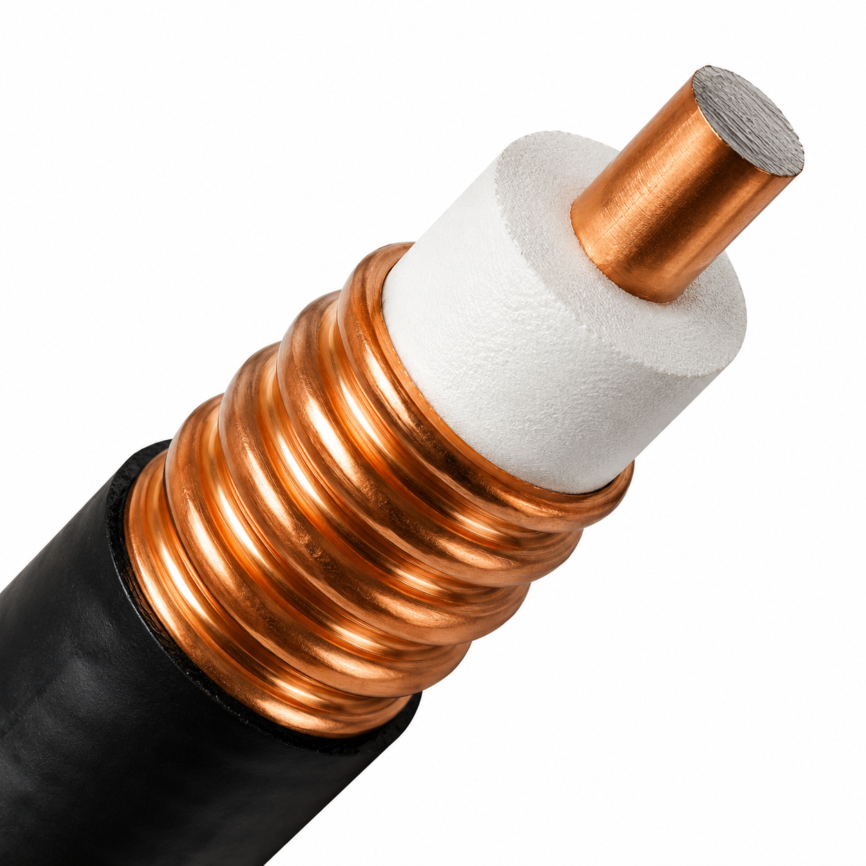
Every cellular tower, distributed antenna system (DAS), and broadcast transmitter site faces a fundamental infrastructure choice: selecting between heavy-duty feeder lines or standard flexible coaxial options. Both carry radio frequency energy across the network, but they are built for entirely different operational roles.
Choosing a corrugated feeder cable provides exceptional signal protection and ultra-low attenuation by utilizing a continuous solid metal shield. Standard braided cables offer flexibility and lower upfront material costs, but they suffer higher signal loss over distance. A corrugated feeder cable dominates long outdoor vertical runs and high-power transmission paths, whereas standard flexible coax excels in short jumper connections and internal cabinet wiring.
The defining feature of a corrugated copper feeder cable is its solid outer conductor, which replaces traditional metal wire braiding with a continuous spiral or annular copper tube. This structural shift delivers three distinct performance advantages:
Lower Signal Attenuation: A solid copper cylinder conducts current with lower electrical resistance than woven wire strands, drastically reducing energy loss over long distances.
Superior Shielding Effectiveness: Solid metal outer tubes yield shielding ratings exceeding 90 dB, eliminating crosstalk and external signal interference in dense antenna locations.
Higher Power Capacity: Solid metal paths dissipate thermal energy far more efficiently, allowing the line to handle higher peak RF power levels without dielectric breakdown.
| Feature Category | Corrugated Copper Feeder Cable | Standard Braided Coaxial Cable |
| Outer Shield | Solid annular/spiral copper tube | Woven wire braid or foil wrapper |
| Attenuation Level | Ultra-low signal loss across long runs | Moderate to high attenuation per meter |
| Shielding Efficiency | Superior (>90 dB RF isolation) | Moderate (60–80 dB depending on braid) |
| Flexibility & Weight | Stiffer build; requires wider bend radius | Highly flexible; tight bend radius |
| Best Application | Tower risers, DAS trunks, outdoor mains | Device jumpers, test equipment, rack interconnects |
While a corrugated feeder cable carries a heavier physical weight and wider minimum bend radius, modern Superflex designs incorporate tighter corrugation pitches to make routing around corners significantly easier during field installation.
Not every transmission line requires a thick corrugated copper feeder cable. System efficiency relies on choosing the right coaxial line for each specific link in the signal path.
Compact Board-to-Antenna Wiring: Internal wireless devices and small IoT gateways rely on ultra-miniature jumper options like a ufl cable to connect internal circuit boards directly to panel-mount antenna jacks.
High-Definition Broadcast Video: Video production environments and digital video routing equipment demand precision 75-ohm lines like a specialized sdi bnc cable to transport uncompressed serial digital signals cleanly without jitter.
Double-Shielded Test and Patch Equipment: Test benches, radio racks, and high-density signal environments benefit from a flexible double-braided rg223 cable, which offers high RF shielding while remaining easy to move and reconfigure.
Tower Risers and Main Antenna Feeds: High-power base station antennas and rooftop installations demand a heavy-duty corrugated feeder cable to bridge long outdoor distances without burning up transmitted power.
Deploying a corrugated feeder cable where distance or shielding demands it—while using flexible options like an rg223 cable, ufl cable, or sdi bnc cable for shorter connections—strikes the ultimate balance between performance and project budget.
System engineers and procurement specialists must verify several core parameters before placing orders for feedline infrastructure:
Operating Frequency Attenuation: Check loss figures at the specific operational band. For instance, a half-inch corrugated feeder cable typically exhibits loss near 13 dB per 100 meters at 900 MHz and around 22 dB per 100 meters at 2.4 GHz.
Characteristic Impedance: Match the line impedance to downstream hardware, utilizing standard 50-ohm paths for RF communications and 75-ohm paths for video broadcasting networks.
Connector Interface Standards: Ensure matching connectors—such as N-Type, 4.3-10, or 7/16 DIN interfaces—are ordered alongside the primary feedline.
Mechanical Bend Limits: Confirm that the cable's minimum bend radius suits the installation pathway, especially when navigating tight conduit turns or rooftop edges.
Solid outer conductors cannot be terminated with generic crimp tools. Attaching hardware to a corrugated copper feeder cable requires specialized strip tools, clean corrugation flares, and precise torque levels. Imprecisely cut outer tubes create metal burrs that cause severe passive intermodulation (PIM) and elevated VSWR reflections.
For tight deployment schedules, specifying factory pre-terminated corrugated feeder cable jumper assemblies eliminates field-termination risks. Factory assemblies arrive pre-tested on vector network analyzers with certified sweep data, ensuring faster site commissioning and fewer installation headaches.
Once installed, a corrugated feeder cable requires minimal upkeep compared to braided alternatives, but routine preventive care extends service life:
Annual Interface Inspection: Check weatherproofing seals and re-verify torque settings on N-Type, 4.3-10, or 7/16 DIN couplings. Loose mechanical interfaces are the leading cause of signal noise in the field.
Jacket Visual Audits: Inspect the outer polyethylene jacket at support clamps where wind movement can rub against mounting hardware.
Baseline VSWR Benchmarking: Record sweep testing baselines at initial commissioning so maintenance crews can detect subtle performance shifts during routine site audits.
Procuring RF signal distribution hardware requires choosing manufacturing partners capable of delivering complete cable assemblies, specialized connectors, and raw feedline stock with full lot traceability. Working with experienced suppliers ensures that every corrugated feeder cable meets strict mechanical tolerances and international manufacturing guidelines.
Partnering with an established manufacturer like Worldpeak gives engineering and procurement teams direct access to extensive production capacity. Supporting a broad range of products—from heavy corrugated copper feeder cable runs to precision internal jumpers like a ufl cable, flexible double-braided rg223 cable, or broadcast-grade sdi bnc cable—Worldpeak delivers factory-tested reliability across the entire transmission path. Working with a certified single-source supplier backed by ISO9001, CE, RoHS, and UL94 standards lowers design risk and maintains stable supply chains for large-scale network builds.
What is the main purpose of a corrugated feeder cable?
A corrugated feeder cable carries high-power RF signals over long distances with minimal loss and high shielding, making it ideal for cellular towers, DAS risers, and broadcast systems.
How does a corrugated copper feeder cable compare to standard coax?
A corrugated copper feeder cable cuts signal loss by 30% to 50% compared to braided coax of similar size while delivering superior RF shielding (>90 dB) and higher power capacity.
Can field crews terminate a corrugated feeder cable with standard crimp tools?
No. Solid outer conductors require dedicated prep tools and specialized connector bodies. Ordering factory pre-terminated assemblies is recommended for fast, error-free site builds.

2026/09/24
Choose a 7 16 connector for high-power RF: compare DIN and Type N, protect PIM margin, and apply field installation checks.

2026/09/24
Compare TNC connector types, specs and applications, including RP-TNC, bulkhead options, vibration performance and adapter selection.

2026/09/24
Understand MMCX connector basics, RF limits, and how to choose the right coaxial interface for compact systems.

2026/09/24
Understand RP-SMA connector polarity, mating rules, frequency checks, and OEM termination options for reliable RF builds.

2026/09/24
Choose the right bnc male connector for RF, CCTV and test systems with clear 50Ω vs 75Ω, type and installation guidance.

2026/09/24
Compare LMR400 specs, cable loss, uses, connectors and RG8/RG213 alternatives with a practical RF loss-budget method.