 EN
EN

What environmental resistance can be customized for OEM rf cable
2026/09/25
Customize an rf high frequency cable for temperature, moisture, corrosion, vibration, flexing, and OEM validation needs.
2026/09/05
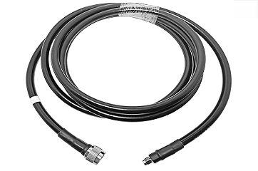
Investing in an outdoor feeder cable for critical telecommunication infrastructure requires strict evaluation of material composition and production precision. In harsh operating environments, small differences in manufacturing accuracy directly determine whether a remote wireless link remains stable or requires endless maintenance. RF site engineers routinely encounter unexpected attenuation spikes, water ingress, and signal reflection, almost all of which stem from substandard cable manufacturing or unverified dielectric components. Evaluating outdoor feeder cable quality goes beyond reading factory datasheets. Every real‑world deployment requires physical testing, structural inspection, and batch verification to protect the link budget over years of continuous exposure.
The internal dielectric layer serves as the baseline for attenuation performance in any outdoor feeder cable. High‑grade assemblies rely on either solid polyethylene or nitrogen‑injected foamed polyethylene. These materials keep dielectric loss low while maintaining dimensional stability under broad thermal fluctuations. When selecting an outdoor feeder cable, dielectric choice determines long‑term signal attenuation across target frequency bands.
Inferior products often substitute cheap PVC blends or low‑density polymers to reduce manufacturing costs. Over 12 to 18 months of outdoor exposure, low‑grade dielectrics absorb ambient moisture through microscopic pores in the outer jacket. This moisture intake causes the dielectric constant to shift dramatically, driving signal attenuation from an acceptable 0.12 dB/m up past 0.35 dB/m at 2.4 GHz. Protecting feeder cable quality requires total avoidance of moisture‑susceptible dielectric compounds.
A proper outdoor cable verification process involves measuring signal loss across the target frequency band and conducting thermal stability checks. Nitrogen‑injected foamed PE dielectrics provide a uniform cellular structure that resists moisture intrusion and maintains physical coax spacing even under extreme flexural stress during installation. Choosing a verified outdoor feeder cable ensures consistent propagation velocity and minimizes signal dampening over multi‑year operational lifespans.
Furthermore, dielectric consistency impacts overall return loss across the entire RF cable run. Uneven foaming density creates local impedance variations that bounce signal energy back toward the transmitter. Thorough outdoor cable verification must include swept frequency analysis to spot subtle dielectric irregularities before field installation begins. High‑quality outdoor feeder cable options consistently present uniform dielectric cores that preserve link budgets even under continuous environmental strain.
A genuine outdoor feeder cable demands robust electromagnetic shielding to operate near high‑power transmission sources or adjacent cellular arrays. The gold standard for shielding construction features a dual‑layer braid‑and‑foil combination with a minimum optical coverage of 95% per layer. Adequate shielding preserves signal‑to‑noise ratios in high‑density RF environments where external interference poses constant operational risks.
Requesting a physical cut‑back sample before committing to high‑volume procurement is a crucial outdoor cable verification practice. Factory audits routinely reveal discrepancies between advertised specs and physical samples. For instance, cables marked as having 98% braid coverage often measure below 80% under microscopic evaluation. Such massive discrepancies severely compromise overall feeder cable quality.
| Shielding Type | Optical Coverage | Typical Shielding Effectiveness (1 GHz) | Primary Vulnerability |
|---|---|---|---|
| Low‑grade Single Braid | 70% – 80% | ~60 dB to 65 dB | Severe RF leakage, low SNR |
| Standard Dual Braid | 85% – 90% | ~75 dB to 80 dB | Flex‑fatigue over repeated bending |
| Premium Braid + Foil | ≥95% per layer | >90 dB | None (optimal isolation) |
A 15 dB drop in shielding effectiveness degrades signal‑to‑noise ratios at the receiver end, leading to dropped packets, reduced throughput, and elevated bit error rates in high‑frequency wireless communications. Proper outdoor cable verification requires lab testing of shielding efficiency across operating spectrums to prevent noise ingress from degrading sensitive network nodes.
In addition to noise immunity, high‑density shielding enhances physical durability. A tight metallic braid supports the inner dielectric layer, preventing crushing or deformation during tight‑radius bends. Maintaining structural symmetry throughout installation preserves feeder cable quality, preventing unexpected impedance mismatches along outdoor jumper runs.
Outdoor cable verification must account for severe environmental exposure, including direct sunlight, salt fog, and extreme temperature variations. An outdoor feeder cable must comply with standards like IEC 60794 or feature a UV‑stabilized linear low‑density polyethylene (LLDPE) or high‑density polyethylene (HDPE) jacket. Weatherproof jacketing represents a vital layer of defense for long‑term outdoor feeder cable performance.
Jackets lacking adequate carbon black content embrittle and crack when subjected to intense solar radiation over time. Micro‑cracks in the outer layer expose the outer shield to moisture, triggering rapid copper oxidation and permanent performance loss. ASTM G154 accelerated UV testing requires the jacket material to withstand 1,000 hours of continuous ultraviolet radiation without surface degradation or reduction in tensile strength.
Evaluating feeder cable quality includes inspecting jacket wall thickness and flexibility at sub‑zero temperatures. Low‑grade jackets freeze and fracture during winter installations, opening direct pathways for rain and humidity to penetrate the shielding layers. A certified outdoor feeder cable with UV‑stabilized LLDPE jacketing maintains mechanical flexibility and weather isolation across harsh seasonal cycles.
Long‑term weather resistance safeguards the internal RF architecture from chemical corrosion and moisture‑driven dielectric deterioration. Rigorous outdoor cable verification protocols prioritize jacket resilience to protect capital investments in telecom towers, remote monitoring stations, and industrial wireless networks.
A top‑grade coaxial line is only as reliable as its connection interfaces. In high‑frequency systems using a TNC cable assembly, physical dimensions must conform strictly to MIL‑STD‑348A specifications for thread geometry, dielectric flushness, and center pin depth. Every TNC cable configuration must maintain precise mechanical tolerances to avoid signal reflection at interface points.
A high‑performance TNC cable requires absolute pin alignment. Pin depth deviations as small as 0.05 mm introduce impedance discontinuities inside the mating plane. This minor physical defect shifts the Voltage Standing Wave Ratio (VSWR) from a crisp 1.15:1 up to 1.45:1 at 6 GHz, wasting over 20% of transmitted RF power as reflected energy. Such power loss severely compromises TNC cable assembly performance in mission‑critical links.
Engineering procurement protocols should insist on swept‑frequency VSWR test data spanning 0.5 GHz to 6 GHz for every batch of TNC cable assemblies. Clean frequency response curves confirm precise soldering, proper crimp sleeve compression, and defect‑free internal pin alignment. Verifying TNC cable quality at the interface level prevents intermittent signal loss caused by vibration or thermal expansion.
Furthermore, moisture sealing at the TNC cable interface requires robust O‑ring integration and heat‑shrink weatherproofing boots. In outdoor installations, moisture entering an unsealed TNC cable connector quickly wicks along the braid, destroying the entire assembly. Rigorous outdoor cable verification must include ingress protection checks (IP67/IP68) on all completed TNC cable assembly units prior to field deployment.
Consistent feeder cable quality depends on disciplined, multi‑stage factory quality control. Reliable manufacturers run comprehensive testing suites on every production lot, combining continuous inline monitoring with batch sampling:
Detailed batch testing reports offer clear verification of feeder cable quality before shipment. Procurement teams should audit these factory records to confirm that every production run complies with technical specifications and environmental resistance benchmarks.
Verifying dielectric purity, confirming true shielding coverage, checking UV stabilization, inspecting connector tolerances, and auditing factory test records form a complete framework for outdoor cable verification. Following these steps helps engineering teams prevent costly field maintenance and protect critical wireless networks. Ensuring strict feeder cable quality at the procurement stage guarantees reliable signal transmission across demanding outdoor applications.
Companies looking to secure high‑performance interconnect solutions can rely on CNRF for fully customized RF assemblies. Supported by advanced automated production systems and complete batch‑level RF testing, CNRF delivers high‑precision TNC cable configurations and custom outdoor feeder cable assemblies designed to meet rigorous telecom standards across tough operating environments.

2026/09/25
Customize an rf high frequency cable for temperature, moisture, corrosion, vibration, flexing, and OEM validation needs.

2026/09/25
Streamline RF equipment assembly lines with custom coaxial jumpers. Reduce line-side rework, ensure precise routing, and boost production efficiency.

2026/09/25
Learn PL-259 connector selection, soldering, weatherproofing, and RF applications for dependable antenna feedlines.

2026/09/25
Confirm impedance for a 90 degree coax connector with an ODM test plan covering VNA setup, VSWR, acceptance criteria, and release records.

2026/09/25
Learn when an n type coax connector can omit extra anti-corrosion treatment and when OEM exposure conditions require it.

2026/09/25
Learn how the custom cable and wire sample process helps ODM buyers validate design, testing, and production readiness.