 EN
EN

What environmental resistance can be customized for OEM rf cable
2026/09/25
Customize an rf high frequency cable for temperature, moisture, corrosion, vibration, flexing, and OEM validation needs.
2026/09/09
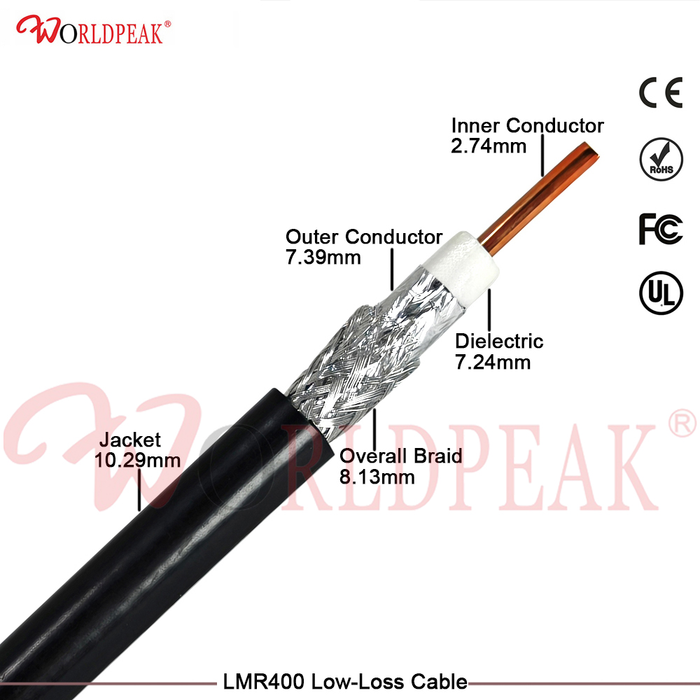
Achieving peak signal efficiency in high-frequency wireless infrastructure depends heavily on choosing an optimal low loss coax. Whether deploying outdoor wireless bridges, land-mobile radio base stations, or cellular coverage extenders, transmission lines must deliver low attenuation without sacrificing flexibility or durability. The lmr 400 antenna cable stands out as a versatile industry benchmark, bridging the performance gap between stiff corrugated hardline cables and high-loss flexible jumper lines. Understanding technical specifications, environmental durability factors, and lmr 400 cable price variables helps engineering teams optimize both link budgets and overall system costs.
The structural design of an lmr 400 antenna cable is engineered specifically to minimize attenuation while keeping the physical profile manageable during field installation. Constructed with a solid copper-clad aluminum or bare copper center conductor measuring 2.74 mm (0.108 inches) in diameter, the core is encapsulated within a gas-injected foam polyethylene dielectric. Dual-layer shielding—combining a 100% coverage bonded aluminum tape with an outer 90% tinned copper braid—provides effective RF shielding exceeding 90 dB. This multi-layer construction delivers strong EMI protection inside noisy urban environments and high-density antenna sites.
Selecting an antenna feed cable involves balancing insertion loss against mechanical bend radius, outer diameter, and lifetime endurance. Comparing standard lmr 400 specs against older coaxial options like RG-213 highlights clear performance advantages across key operational metrics.
| Performance Parameter | LMR-400 Low Loss Coax | Legacy RG-213 Cable |
|---|---|---|
| Characteristic Impedance | 50 Ω | 50 Ω |
| Center Conductor Diameter | ~2.74 mm (Solid BCCAI/BC) | ~2.26 mm (Stranded BC) |
| Dielectric Material | Foam Polyethylene (PE) | Solid Polyethylene (PE) |
| Outer Diameter (OD) | ~10.29 mm (0.405 in) | ~10.30 mm (0.405 in) |
| Atten. @ 900 MHz (per 100m) | ~12.8 dB | ~27.0 dB |
| Atten. @ 2400 MHz (per 100m) | ~22.2 dB | ~48.0 dB |
| RF Shielding Effectiveness | > 90 dB | ~60 dB |
| Minimum Bend Radius | ~25.4 mm (1.0 in) | ~50.8 mm (2.0 in) |
Replacing older RG-213 runs with a modern lmr 400 antenna cable cuts signal loss by more than half across UHF and microwave frequencies. For vertical tower feedlines and long antenna runs, reducing attenuation directly increases radiated power and improves receiver sensitivity across all operating bands.
Evaluating the lmr 400 cable price across commercial projects requires considering raw materials, jacket classifications, termination requirements, and order volumes. Several key factors impact total cost calculations:
A typical 15-meter pre-tested assembly costs significantly less than heavy corrugated hardline cables, making low loss coax a practical choice for budget-conscious wireless upgrades.
A regional enterprise facility needed to upgrade a 2.4 GHz wireless network link connecting two production buildings located 120 meters apart. The existing feedline setup utilized aged RG-8 coax running from indoor access points to roof-mounted directional antennas, creating significant signal attenuation that caused frequent packet drops during peak operating hours.
Replacing the 20-meter indoor-to-outdoor feedlines with high-grade lmr 400 antenna cable assemblies reduced overall line loss by approximately 5.2 dB per side. The increased system link margin restored stable connection speeds, eliminated link drops, and avoided the significant capital expenses associated with installing active fiber optic extenders.
Calculating system link budgets requires reviewing attenuation profiles across operating frequencies. Because attenuation increases at higher frequencies, checking exact loss curves ensures adequate transmitter margin.
For cable lengths exceeding 30 meters at frequencies above 3.5 GHz, engineers often evaluate lower-loss option sizes like LMR-600 to preserve signal strength before reaching receiver front-ends.
Proper field handling prevents physical damage and protects signal stability over long service lifetimes. Adhering to established installation procedures reduces field maintenance requirements and prevents premature cable failures:
Adhering to these practical installation guidelines ensures long-term operational reliability across demanding outdoor environments.
Sourcing reliable feedline assemblies requires consistent raw material standards, precise mechanical crimping, and complete factory validation. Unverified cable imports often feature uneven braid coverage or substandard dielectric densities, resulting in hidden impedance variations across operating frequencies.
WORLDPEAK supports demanding RF infrastructure projects by manufacturing precision-engineered low loss coax products, specialized feedline assemblies, and high-frequency connector lines. Utilizing automated stripping equipment, automated crimping workflows, and precision testing setups, WORLDPEAK delivers custom lmr 400 antenna cable assemblies tailored to exact length and connector requirements. Every product lot undergoes 100% VSWR testing, return loss evaluation, and physical quality inspection, providing reliable performance and competitive lmr 400 cable price structures for telecom operators, defense contractors, and industrial system integrators worldwide.

2026/09/25
Customize an rf high frequency cable for temperature, moisture, corrosion, vibration, flexing, and OEM validation needs.

2026/09/25
Streamline RF equipment assembly lines with custom coaxial jumpers. Reduce line-side rework, ensure precise routing, and boost production efficiency.

2026/09/25
Learn PL-259 connector selection, soldering, weatherproofing, and RF applications for dependable antenna feedlines.

2026/09/25
Confirm impedance for a 90 degree coax connector with an ODM test plan covering VNA setup, VSWR, acceptance criteria, and release records.

2026/09/25
Learn when an n type coax connector can omit extra anti-corrosion treatment and when OEM exposure conditions require it.

2026/09/25
Learn how the custom cable and wire sample process helps ODM buyers validate design, testing, and production readiness.