 EN
EN

LMR-400 Coax: Outdoor Antenna Run Sizing Guide
When telecom infrastructure procurement teams evaluate feedline for a new outdoor antenna installation, the conversation typically returns to one cable type: the LMR 400 coaxial cable. Buyers who treat cable selection as an afterthought tend to revisit it during commissioning — often after unnecessary signal loss has already been designed into the system.
This guide covers the cable structure, impedance selection logic, attenuation budgeting, and installation requirements that determine whether an LMR-400 coaxial cable run delivers what a system needs or becomes the weak link in the RF chain.
LMR-400 Cable Construction: What the Layers Actually Do
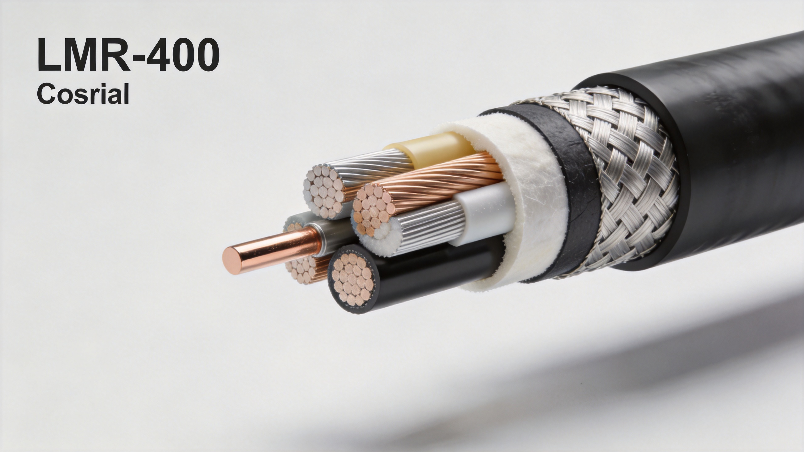
The LMR 400 coaxial cable uses a four-layer construction that drives its outdoor performance advantage over legacy RG-8 and RG-213 type cables.
- Inner conductor: Solid copper-clad aluminum (CCA) center conductor. The solid core — rather than stranded — is critical for consistent impedance at RF frequencies.
- Foam polyethylene dielectric: Low-density foam PE reduces dielectric loss compared to solid PE, which is one of the main reasons LMR-400 achieves lower attenuation per unit length than older cable types.
- Braid and foil shield: Aluminum foil combined with tinned copper braid provides approximately 90 dB of RF shielding effectiveness — significantly reducing signal leakage and protecting against ingress interference in electrically noisy environments.
- UV-resistant polyethylene jacket: The black PE outer jacket resists UV degradation, making it suitable for direct sunlight exposure on rooftops, towers, and mast installations without additional conduit in many configurations.
For buyers familiar with the lmr 400 kabel designation in European procurement contexts, the construction and performance specification is the same — "kabel" is simply the German-language term used in that market for the same cable family.
50 Ohm vs. 75 Ohm: The Impedance Selection Procurement Teams Need
A common question when specifying LMR 400 coaxial cable for the first time: 50-ohm or 75-ohm? For outdoor antenna runs in wireless infrastructure, industrial wireless, and telecom base station applications, 50 ohm is the correct specification.
50-ohm impedance is the RF industry standard for transmit and receive antenna systems — a practical compromise that optimizes for power handling. Almost all RF connectors in wireless infrastructure, including SMA, N-type, and 7/16 DIN, are standardized at 50 ohms. 75-ohm coaxial cable is the standard for broadcast television distribution and CATV signal distribution, where it matches the impedance of antenna and distribution equipment in that ecosystem. Connecting a 75-ohm cable into a 50-ohm antenna system creates a mismatch that increases reflected power and degrades system performance.
The procurement rule: if your equipment uses SMA, N-type, TNC, or BNC connectors in an RF transmit/receive application, specify 50-ohm LMR 400 coaxial cable. 75-ohm cable is appropriate only for CATV or satellite IF distribution — a different product family entirely.
Sizing the Run: Attenuation Budget for Outdoor Installations
The LMR-400 coaxial cable has a published attenuation of approximately 4.25 dB per 100 feet (about 1.4 dB per 10 meters) at 1 GHz — measurably lower than RG-213 at approximately 1.0 dB per 100 feet, a meaningful difference in longer runs.
How attenuation scales across common wireless frequencies:
| Frequency | LMR-400 Attenuation (approx.) | Typical Use Case |
|---|---|---|
| 900 MHz | ~3.5 dB / 100 ft | Sub-GHz IoT, GSM coverage |
| 1 GHz | ~4.25 dB / 100 ft | GPS, L-band, cellular feeder |
| 2.4 GHz | ~6.8 dB / 100 ft | Wi-Fi, 2.4 GHz ISM band |
| 5 GHz | ~10.0 dB / 100 ft | Wi-Fi 5 GHz, UNII bands |
For runs longer than 50 feet at frequencies above 2 GHz, the attenuation from an LMR 400 coaxial cable run should be entered into the link budget before installation — not estimated. Buyers who skip this step sometimes find the cable run consumes margins they had reserved for other system losses.
Standard LMR-400 vs. LMR-400-UF: Choosing the Right Variant
The lmr 400 ultra flex variant (LMR-400-UF) is a modified construction designed for installations requiring tighter routing paths. Understanding the differences matters when specifying cable for different site types:
- Standard LMR-400: Well-suited for straight or gently routed outdoor runs — tower-mounted feeder drops, rooftop runs with minimal bends, and conduit-protected horizontal runs. Delivers consistent low-loss performance in fixed-installation geometries.
- LMR-400-UF (Ultra Flex): Better for installations requiring routing flexibility — through cable trays, around enclosures, or where installers cannot pre-form the cable path before pulling. Trades a marginal amount of loss performance for significantly better bending compliance.
For most outdoor antenna feeder runs, standard LMR-400 is the appropriate specification. The UF variant is more commonly used in distributed antenna systems and equipment rooms where routing paths are constrained.
Installation Notes: Bend Radius and Stripping Tool Requirements
Two parameters consistently separate well-specified LMR 400 coaxial cable runs from poorly executed ones.
Bend radius requirements:
- Standard LMR-400 minimum bend radius: 1 inch (25.4 mm) for a single fixed bend during installation.
- Dynamic (repeated bending) minimum: 4 inches (approximately 100 mm) — relevant if cable will be coiled, moved during service, or flexed periodically.
- Violating the minimum bend radius deforms the foam dielectric, alters local impedance, and creates a reflection point in the cable. This damage is not visible externally.
Stripping tool selection: The LMR-400 coaxial cable requires a properly sized stripping tool — using the wrong tool or stripping by hand risks cutting through the braid into the dielectric, creating a shielding gap at the connector termination. A dedicated lmr 400 stripping tool sized for this cable type ensures clean, repeatable connector preparation at every termination. This is a procurement item installation teams sometimes overlook until the first connector prep fails inspection.
Sourcing LMR-400 Cable and Pre-Terminated Assemblies
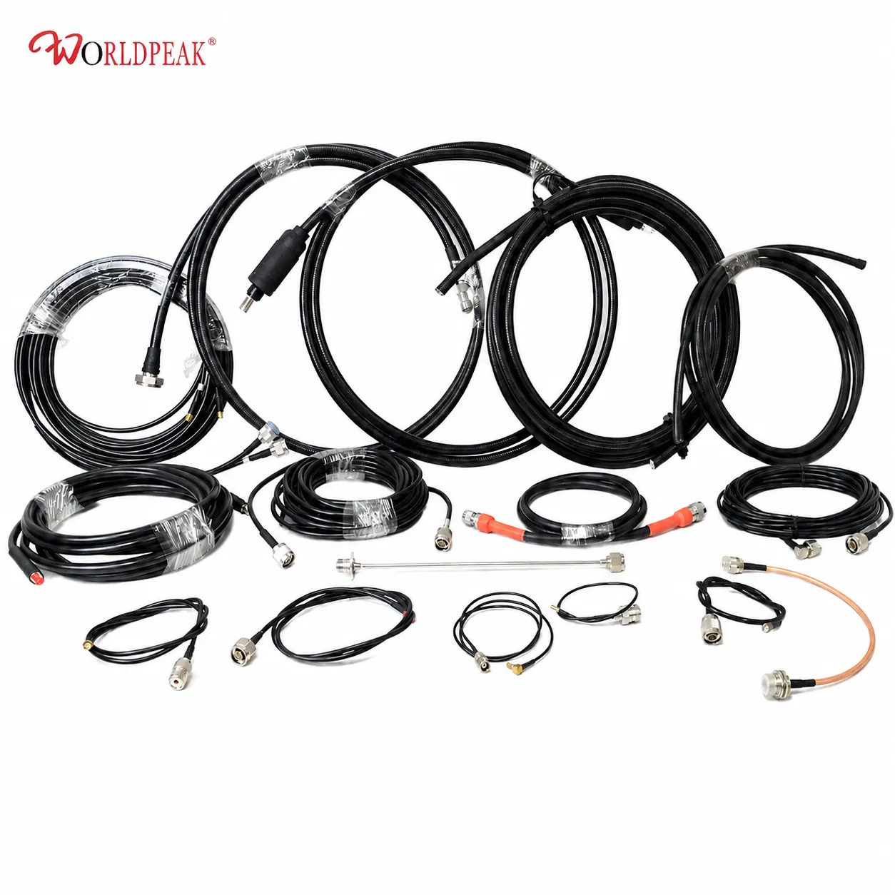
For buyers sourcing LMR 400 coaxial cable in bulk for network rollout projects or pre-terminated assemblies for single-site installations, Worldpeak offers both the raw cable and factory-assembled, tested options.
The LMR400 Low-Loss 50 Ohm Coaxial Cable provides the 50-ohm, UV-rated outdoor cable for installations where field termination is preferred or custom run lengths are required.
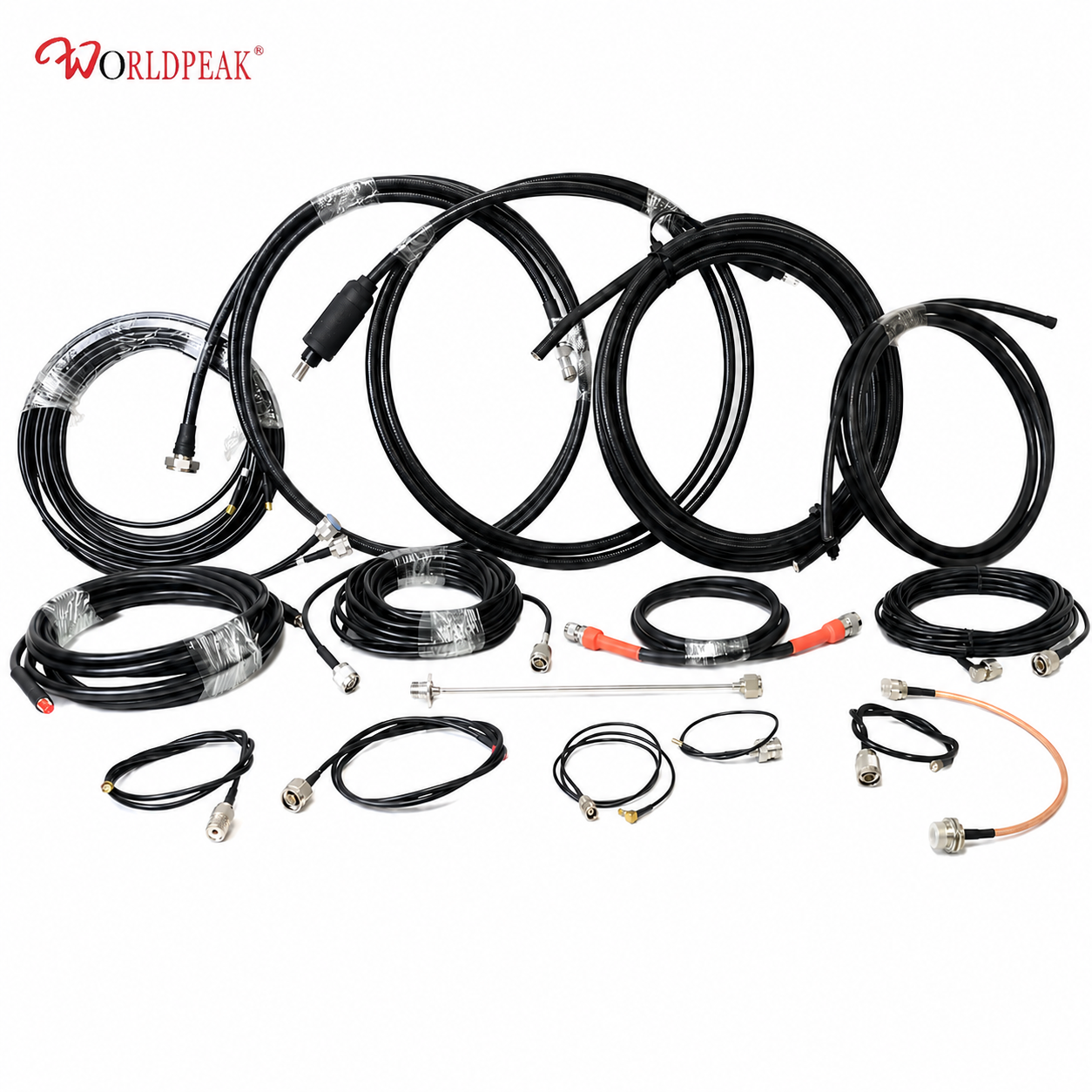
For projects where reducing installation variability and site labor are priorities, the Worldpeak LMR 400 Pre-Terminated Cable Assembly provides factory-terminated, tested assemblies ready to connect, with confirmed electrical performance at both ends.
Engineering teams evaluating alternative cable types alongside LMR-400 can reference the Worldpeak RG400 50-Ohm Coaxial Cable: Engineering Data & Selection Guide for specification comparisons across the 50-ohm flexible cable product range.
Summary: Key Sizing Decisions Before Specifying LMR-400
Before finalizing the LMR 400 coaxial cable specification for an outdoor antenna run, confirm:
- Impedance match: 50 ohm for RF antenna systems.
- Run length and frequency: Calculate attenuation at operating frequency and verify it fits the system link budget.
- Variant selection: Standard LMR-400 for fixed outdoor runs; LMR-400-UF where routing flexibility is needed.
- Bend radius compliance: Plan routing above 1-inch (fixed) or 4-inch (dynamic) minimum bend radius.
- Stripping tooling: Confirm installation team has an LMR-400-rated stripping tool before pulling cable.
- Pre-terminated vs. field-terminated: Factory assemblies reduce on-site variability; field termination allows custom lengths and routing adjustments.
Getting these six parameters confirmed before procurement prevents the cable-related performance issues that appear during network commissioning. Once the cable is pulled and connected, correcting impedance or routing mistakes requires a full rework.





