 EN
EN

7/16 DIN Connector Guide: High-Power RF Standard
2026/09/24
Choose a 7 16 connector for high-power RF: compare DIN and Type N, protect PIM margin, and apply field installation checks.
2026/09/02
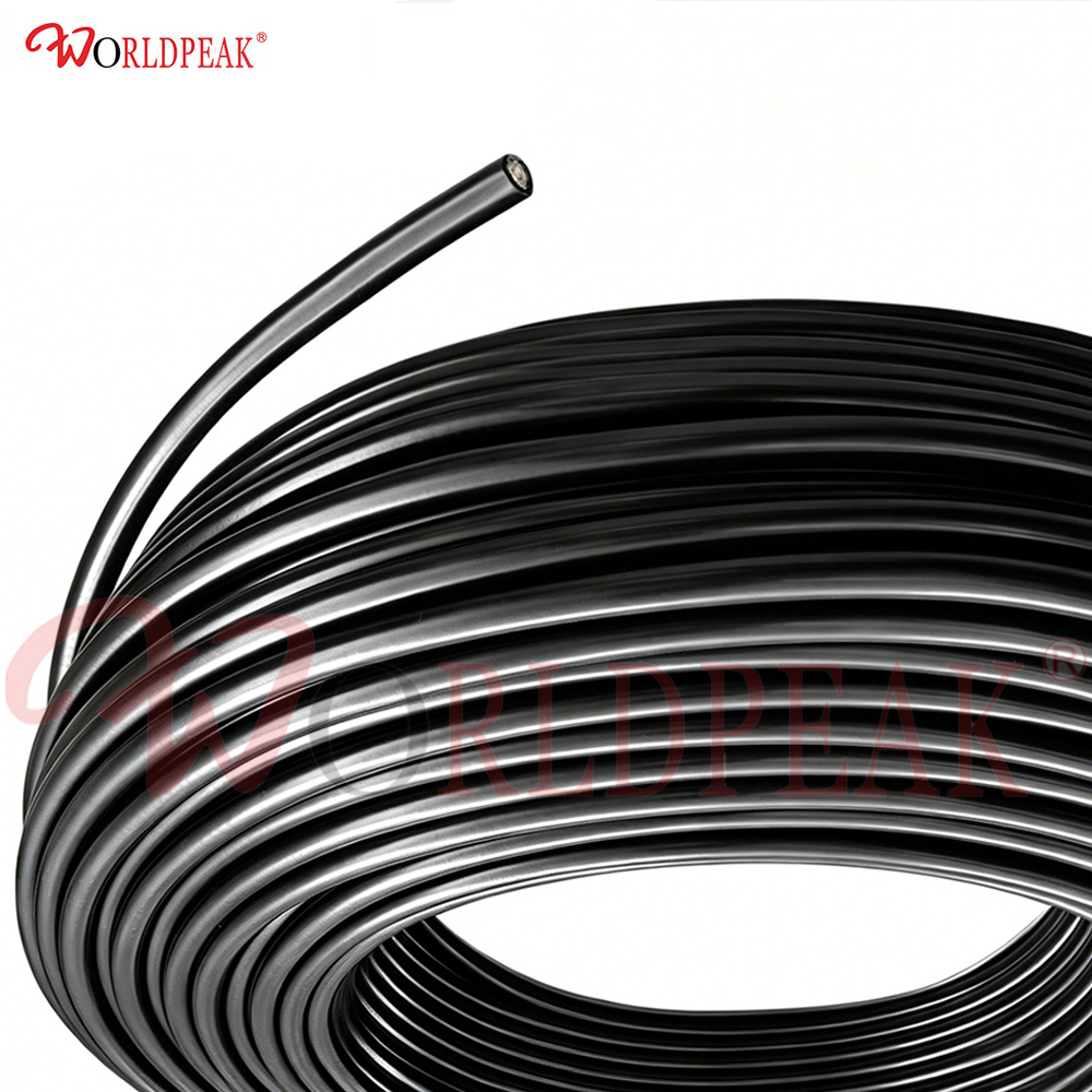
Signal loss over distance remains a stubborn hurdle in high-frequency wireless engineering. Whenever cable runs push past 20 or 30 meters, selecting the right transmission line becomes the single biggest decision impacting total system performance. Drop too much power along the line, and even the most expensive antennas or high-gain amplifiers will fail to deliver clean data throughput.
That balance between flexibility, physical durability, and low signal attenuation is precisely why lmr 400 low loss coaxial cable has turned into an industry standard across telecom, outdoor Wi-Fi, marine installations, and industrial wireless links.
Every coaxial line exhibits inherent energy loss. As radio frequency signals travel down a conductor, dielectric absorption and physical resistance turn part of that energy into waste heat. This continuous drop in signal strength is measured as RF cable attenuation, typically calculated in decibels per 100 meters or 100 feet.
If RF cable attenuation runs too high, the signal arriving at the antenna drops below the receiver's threshold. At higher frequencies—like 2.4 GHz Wi-Fi or 5G sub-6 GHz bands—standard coaxial cable types like RG58 or RG213 lose energy at an alarming rate. Upgrading to a specialized low loss cable setup ensures that transmitter power reaches the radiating element intact.
Engineers created LMR400 as a direct drop-in replacement for stiff, hard-to-bend corrugated cables and high-loss legacy options like RG8 or RG213. A close look at its physical construction shows why this coaxial cable outperforms traditional flexible lines so dramatically:
Solid Copper-Clad Aluminum Center Conductor: Combines excellent high-frequency conductivity with lightweight handling and lower DC resistance.
Foam Polyethylene Dielectric: Gas-injected foam dielectric reduces energy absorption far better than solid polyethylene dielectrics, keeping dielectric loss minimal.
Dual Shielding Layer: An outer layer combining aluminum tape bonded to the dielectric plus a dense tinned copper braid provides outstanding shielding effectiveness exceeding 90 dB.
Weatherproof Outer Jacket: Heavy-duty polyethylene or UV-protected materials shield the internal layers from moisture, sunlight, and extreme outdoor temperature swings.
Comparing physical specs only tells part of the story. The real proof lies in comparing RF cable attenuation across common operational bands.
| Frequency Band | LMR 400 Low Loss Coaxial Cable Attenuation | RG213 Attenuation | RG58 Attenuation | Performance Difference |
| 150 MHz (VHF) | ~2.8 dB / 100m | ~5.5 dB / 100m | ~12.5 dB / 100m | Over 50% loss reduction |
| 450 MHz (UHF) | ~4.9 dB / 100m | ~9.5 dB / 100m | ~22.0 dB / 100m | Over 45% loss reduction |
| 900 MHz (ISM / Cellular) | ~6.8 dB / 100m | ~12.0 dB / 100m | ~28.0 dB / 100m | Over 40% loss reduction |
| 1800 MHz (PCS / LTE) | ~9.8 dB / 100m | ~17.0 dB / 100m | ~40.0 dB / 100m | Over 40% loss reduction |
| 2500 MHz (Wi-Fi / 5G) | ~11.8 dB / 100m | ~20.0 dB / 100m | ~48.0 dB / 100m | Over 40% loss reduction |
Looking at a standard 50-meter cable run operating at 900 MHz puts these numbers in perspective:
Using RG58 results in roughly 14 dB of signal loss, meaning less than 4% of transmitter power reaches the antenna.
Using RG213 drops loss to 6 dB, delivering roughly 25% of initial power.
Switching to lmr 400 low loss coaxial cable limits loss to just 3.4 dB, leaving over 54% of usable power delivered straight to the feedhead.
That single upgrade yields over 10 dB of extra link margin—equivalent to boosting transmitter power tenfold without adding active amplifiers or risking regulatory power violations.
Because LMR400 hits the sweet spot between low RF cable attenuation and manageable bending radius, it handles demanding roles across numerous industries:
Feeder runs climbing up mobile towers or connecting remote radio units require low loss cable solutions to handle 4G LTE and 5G signals cleanly over 30 to 80 meters.
Wireless Internet Service Providers rely on LMR400 coaxial cable assemblies to connect base station radios to high-gain sector or dish antennas across long mast runs.
In building setups where signals pass through hundreds of feet of plenum space, low loss cable guarantees consistent signal distribution across all interior coverage nodes.
Smart grid monitoring, oil pipeline telemetry, and remote automation platforms depend on LMR400 to maintain uninterrupted communications in harsh environments.
Even the best coaxial cable drops in performance if improper installation practices damage the dielectric or compromise the shielding layer. To keep RF cable attenuation low over time, follow these field guidelines:
LMR400 allows a minimum bend radius of 25.4 mm (1 inch) for repeated flexing and 12.7 mm (0.5 inch) for single installation bends. Bends tighter than this can crush the internal foam dielectric, changing the 50-ohm characteristic impedance and spiking VSWR.
Improperly fitted connectors introduce impedance bumps that reflect signal power back toward the source:
Cut the coaxial cable clean and perfectly square using dedicated coax prep tools.
Trim the center conductor, foam dielectric, and outer braid to exact manufacturer specifications.
Use precision-matched crimp or clamp connectors (like N-type or SMA fittings) engineered for LMR400 outer dimensions.
Perform a firm pull test to confirm mechanical grip before weatherproofing.
Water ingress ruins low loss cable assemblies faster than physical wear. Moisture trapped in the braid spikes RF cable attenuation rapidly:
Wrap connector joints with self-amalgamating butyl rubber tape followed by heavy-duty electrical tape.
Form drip loops right before entry ports to guide rainwater away from indoor enclosures.
Anchor vertical cable runs every 1 to 1.5 meters using UV-resistant hardware to prevent wind whip and strain.
A regional wireless provider operating across expansive rural terrain encountered severe signal dropouts on long-range point-to-point links. Base stations equipped with legacy 100-meter RG213 cable runs lost nearly 12 dB of signal before reaching the sector antennas at 900 MHz.
Replacing those aging lines with precision-terminated lmr 400 low loss coaxial cable slashed line losses from 12 dB down to 6.8 dB. That 5.2 dB recovery immediately translated into a 40% increase in average data throughput and cut connection drops across fringe subscriber locations by more than half—all achieved without replacing radios or adding powered boosters.
Investing in LMR400 low loss cable yields long-term dividends by safeguarding link reliability and eliminating costly tower climbs. Slashing line loss preserves signal integrity, optimizes system operating margins, and ensures network installations run reliably for years to come.
Worldpeak delivers robust RF cabling solutions, manufacturing precision-engineered LMR400 jumper cables, high-performance coaxial connector lines, and tested RF assemblies built for global telecom networks, outdoor wireless systems, and industrial infrastructure. Whether setting up complex antenna arrays or retrofitting existing feeder lines, Worldpeak brings trusted supply chain efficiency and rigorous product testing to every project.

2026/09/24
Choose a 7 16 connector for high-power RF: compare DIN and Type N, protect PIM margin, and apply field installation checks.

2026/09/24
Compare TNC connector types, specs and applications, including RP-TNC, bulkhead options, vibration performance and adapter selection.

2026/09/24
Understand MMCX connector basics, RF limits, and how to choose the right coaxial interface for compact systems.

2026/09/24
Understand RP-SMA connector polarity, mating rules, frequency checks, and OEM termination options for reliable RF builds.

2026/09/24
Choose the right bnc male connector for RF, CCTV and test systems with clear 50Ω vs 75Ω, type and installation guidance.

2026/09/24
Compare LMR400 specs, cable loss, uses, connectors and RG8/RG213 alternatives with a practical RF loss-budget method.