 EN
EN

What environmental resistance can be customized for OEM rf cable
2026/09/25
Customize an rf high frequency cable for temperature, moisture, corrosion, vibration, flexing, and OEM validation needs.
2026/09/08
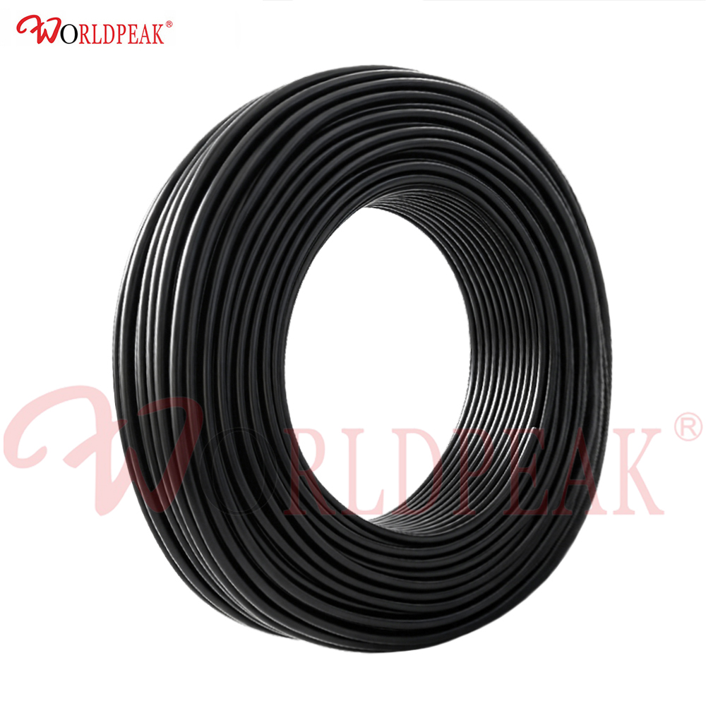
Designing a high-performance wireless system requires balancing link budget margins with real-world physical routing demands. Signals running through transmission lines lose power due to conductor resistance and dielectric heating. For field technicians and RF engineers, getting accurate signal attenuation numbers is essential to prevent costly coverage dead zones.
Flexible coax lines like LMR 400 UF coax cable have become industry mainstays for cellular infrastructure, Wi-Fi backhaul, and two-way radio installations. Combining low insertion loss with a stranded center conductor, this cable grade bends easily around obstacles without compromising overall signal integrity.
Signal attenuation in coaxial transmission lines rises alongside operating frequency. Lower frequencies experience less signal attenuation, while higher microwave frequencies suffer higher cable losses per foot. Knowing exact signal attenuation data helps engineers calculate accurate link budget estimates before climbing a tower or pulling cable through conduits.
Under standard operating conditions (50-ohm systems at 20 degrees Celsius), LMR 400 UF coax cable delivers impressive attenuation resistance across common frequency bands:
Beyond operating frequency, ambient temperature directly influences signal attenuation. As temperatures rise, copper resistance increases and dielectric materials absorb more energy. For every 10 degrees Celsius increase above room temperature, conductor losses rise by approximately 0.2 percent and dielectric losses increase by 0.4 percent. In exposed outdoor installations where dark jackets reach high temperatures under direct sunlight, thermal expansion can add 1 to 2 dB of unplanned signal attenuation over a long run.
Choosing the right transmission line usually involves comparing physical size, cost, and electrical efficiency. Comparing LMR 400 UF coax cable against smaller alternatives like LMR 240 coax cable shows clear performance gaps across different bands.
Reviewing a comprehensive coax cable loss table helps determine when a thicker cable becomes necessary to preserve signal budget.
| Frequency (MHz) | LMR 400 UF Coax Cable (dB/100ft) | LMR 240 Coax Cable (dB/100ft) | Attenuation Difference (dB) |
|---|---|---|---|
| 150 MHz | 1.5 | 2.8 | 1.3 |
| 450 MHz | 2.7 | 4.8 | 2.1 |
| 900 MHz | 3.9 | 6.8 | 2.9 |
| 1800 MHz | 5.6 | 9.8 | 4.2 |
| 2400 MHz | 6.6 | 11.5 | 4.9 |
| 5800 MHz | 10.8 | 18.5 | 7.7 |
Analyzing this coax cable loss table reveals that LMR 240 coax cable exhibits significantly higher signal attenuation at every step. At 900 MHz, LMR 240 coax cable shows 6.8 dB of loss per 100ft versus only 3.9 dB for LMR 400 UF coax cable. Over a 100-foot span, using LMR 240 coax cable drops twice as much RF energy into heat, making LMR 400 UF coax cable the superior choice for longer cable runs.
Performing a thorough LMR cable comparison requires evaluating mechanical trade-offs alongside raw electrical data.
Real-world deployments demonstrate how selecting the right cable grade impacts both system cost and field installation timelines.
Consider a wireless broadband tower installation requiring a 150-foot run from base station hardware up to top-mounted sector antennas operating at 3.5 GHz. Utilizing LMR 400 UF coax cable generates an overall signal attenuation of roughly 13.2 dB across the entire path. Substituting LMR 240 coax cable across that same distance yields a massive 22.5 dB signal attenuation—a 9.3 dB penalty that degrades receiver sensitivity and requires higher transmitter power outputs.
From an installation perspective, ultra-flexible stranded construction eliminates tight cable pulling issues. Riggers can easily maneuver LMR 400 UF coax cable through crowded cable trays and conduit elbows without risking impedance spikes from crushed dielectrics. This flexibility speeds up field assembly work by nearly a third while reducing the need for costly external junction boxes.
Even the lowest loss cable loses performance if paired with poorly assembled connectors. LMR 400 UF coax cable interfaces cleanly with standard N-type, SMA, TNC, and BNC connector designs engineered for 0.405-inch coaxial geometry.
To guarantee rated signal attenuation performance across critical infrastructure projects, many operators rely on pre-terminated jumper runs. Suppliers like WORLDPEAK provide custom-length LMR 400 UF coax cable assemblies fitted with factory-installed, weather-sealed connectors. Every jumper undergoes automated network analyzer testing to verify VSWR, insertion loss, and mechanical durability before deployment. Partnering with experienced coaxial assembly specialists like WORLDPEAK helps engineering teams maintain reliable link budgets across telecom, broadcast, and industrial wireless networks worldwide.

2026/09/25
Customize an rf high frequency cable for temperature, moisture, corrosion, vibration, flexing, and OEM validation needs.

2026/09/25
Streamline RF equipment assembly lines with custom coaxial jumpers. Reduce line-side rework, ensure precise routing, and boost production efficiency.

2026/09/25
Learn PL-259 connector selection, soldering, weatherproofing, and RF applications for dependable antenna feedlines.

2026/09/25
Confirm impedance for a 90 degree coax connector with an ODM test plan covering VNA setup, VSWR, acceptance criteria, and release records.

2026/09/25
Learn when an n type coax connector can omit extra anti-corrosion treatment and when OEM exposure conditions require it.

2026/09/25
Learn how the custom cable and wire sample process helps ODM buyers validate design, testing, and production readiness.