 EN
EN

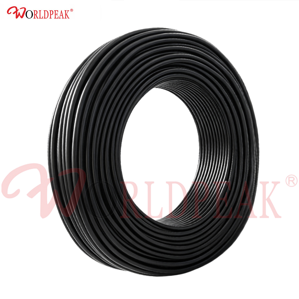
LMR400 Cable: Performance Specs and Uses
The insertion loss figure in the datasheet is a useful starting point—actually, it is more than that when you are evaluating an LMR400 cable for a specific deployment. LMR-400 is a 50-ohm flexible coaxial cable engineered to deliver low signal attenuation across a wide frequency range, making it one of the most widely specified cables for professional RF infrastructure work. Whether you are extending a Wi-Fi antenna, feeding a cellular base station, or running a satellite uplink line, the performance of your LMR400 cable directly determines how much signal margin you have left at the far end of the run.
LMR400 Cable: Key Performance Specifications
LMR-400 operates at 50 ohms impedance with a solid center conductor, a foam polyethylene dielectric, and a UV-resistant PE jacket. The outer diameter is 0.400 inches (10.3 mm), which gives the lmr400 cable its name. RF shielding effectiveness reaches 90 dB, and the maximum operating temperature is 85°C—sufficient for most outdoor and equipment-room environments.
Attenuation figures per 100 feet at commonly used frequencies:
| Frequency | Attenuation (per 100 ft) | Typical Application |
|---|---|---|
| 900 MHz | ~4.0 dB | Cellular backhaul, IoT gateways |
| 1 GHz | 4.25 dB | General RF reference point |
| 2.4 GHz | ~6.5 dB | Wi-Fi 2.4 GHz antenna extension |
| 5.8 GHz | 10.8 dB | Wi-Fi 5 GHz / outdoor point-to-point |
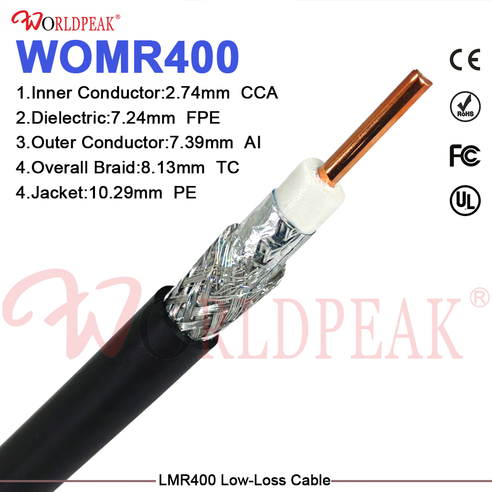
The maximum rated frequency is 8 GHz, covering the full 5 GHz Wi-Fi band and most cellular bands currently deployed. These numbers come from published manufacturer data and remain consistent across standard LMR400 cable constructions from different producers.
How LMR400 Cable Compares to RG8 and RG213
Shifting from single-parameter to multi-constraint evaluation changes how you read a cable comparison. It is not enough to note that an LMR400 cable has lower attenuation than RG8 or RG213—you also need to consider jacket durability, bend radius, and connector termination options before selecting a cable for a specific installation.
| Parameter | LMR400 Cable | RG8 / RG213 |
|---|---|---|
| Impedance | 50 ohm | 50 ohm |
| Attenuation at 1 GHz | 4.25 dB/100 ft | ~6.0–7.0 dB/100 ft |
| Max frequency | 8 GHz | ~3 GHz |
| Shielding | 90 dB | ~60–70 dB |
| Jacket | UV-resistant PE, outdoor-rated | PVC or PE, limited UV stability |
| Flexibility | Good; minimum bend radius ~25 mm | Stiffer; limited in tight cable trays |
| Direct burial variant | Available (LMR-400-DB) | Less common |
LMR400 cable is a recognized drop-in replacement for RG-8/9913, offering meaningfully lower loss over the same run length. For a 50-foot antenna feedline at 2.4 GHz, the difference in attenuation between an LMR400 cable run and a typical RG213 run translates directly to system link margin. At 5.8 GHz, the gap widens further, which is why LMR-400 is consistently specified over legacy cables for modern Wi-Fi infrastructure and cellular feeder lines.
One distinction that comes up in sourcing discussions: LMR400 cable is a 50-ohm RF communications cable, not a consumer-grade tv aerial cable built for 75-ohm TV distribution. A tv aerial cable uses a different impedance, and installing one in a 50-ohm RF system introduces mismatch loss and elevated VSWR regardless of the stated attenuation rating. If the application is RF communications, a tv aerial cable does not substitute for LMR400 cable in any frequency range.
Applications: Where LMR400 Cable Delivers the Most Value
Wi-Fi Antenna Extension
Indoor access points often cannot be positioned where coverage is needed. An LMR400 cable allows an antenna to be moved away from the access point by 10–30 meters with manageable loss. At 5.8 GHz, a 30-foot LMR400 cable run introduces approximately 3.2 dB of cable loss—far lower than the 5.0–6.0 dB you would see with a lower-grade coaxial alternative. The coax cable outlet placement at the antenna end matters here: mounting a weatherproof coaxial cable fittings assembly at the building entry point eliminates moisture ingress that would otherwise degrade connector performance over time.
Cellular Base Station Feeders
Cellular installers routinely use LMR400 cable for tower-to-equipment room runs where the antenna is elevated and the radio is at ground level. The combination of low attenuation at 900 MHz–2.1 GHz, 90 dB shielding, and an outdoor-rated jacket makes LMR400 cable a practical choice for feeder lengths in the 15–50 meter range. Longer runs typically step up to 1/2-inch superflexible or corrugated cable, but LMR400 cable handles the majority of small-cell and rooftop installations at this scale.
Satellite Ground Station Links
Satellite Ku-band and Ka-band communications require cables that maintain shielding integrity and low VSWR from the dish to the indoor unit. LMR400 cable is routinely used in the L-band (950–2150 MHz) portion of satellite IF distribution, where its attenuation and shielding figures are well within system link budget tolerances.
Connector Compatibility and Coaxial Cable Fittings
LMR400 cable is compatible with N-type, SMA, TNC, BNC, and 7/16 DIN connectors when the correct LMR-400-rated terminations are used. Proper coaxial cable fittings selection affects both the RF performance and the mechanical durability of the assembly. Each additional connector in an RF chain adds roughly 0.1–0.2 dB depending on connector type, frequency, and installation quality—so a cable run with four connection points can lose an additional 0.4–0.8 dB beyond the cable attenuation alone.
At each coax cable outlet on the run, the mechanical fit of the coaxial cable fittings to the LMR400 cable jacket and center conductor matters as much as the electrical specifications. Loose or mismatched coaxial cable fittings allow water ingress in outdoor installations, which degrades the center conductor and braid contact over time and raises insertion loss above the rated cable value.
For installations where the LMR400 cable must be terminated at both ends before the run is measured, pre-terminated assemblies are often more reliable than field-terminated connections. A pre-made cable assembly with factory-tested insertion loss removes the variability of on-site connector installation and provides documented performance data at the time of delivery.
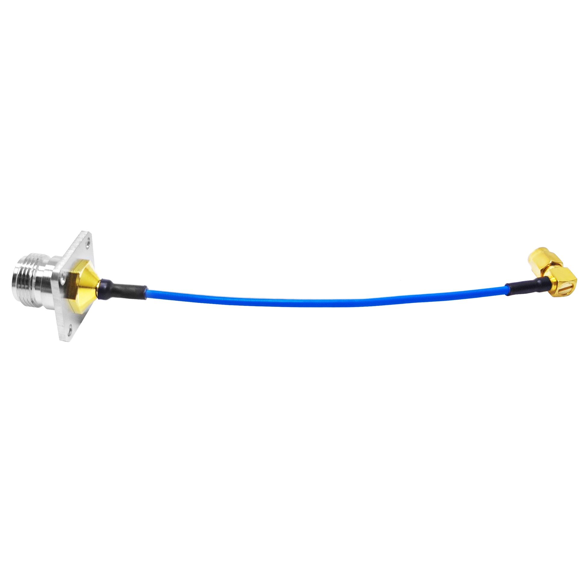
Worldpeak's LMR400 Low-Loss 50 Ohm Coaxial Cable provides bulk LMR400 cable in custom lengths suited to infrastructure feeder and antenna extension applications. For projects requiring ready-to-install assemblies, the Worldpeak SS402 Pre-Terminated Cable Assembly offers factory-terminated coaxial assemblies with per-assembly electrical testing included. Where a thinner, lighter alternative is needed for equipment-rack internal routing, the Worldpeak RG196 50-Ohm Coaxial Cable covers shorter, lower-loss-budget connections within an enclosure.
Loss Budget Calculation Reference for Integrators
A basic loss budget calculation for an LMR400 cable run follows this structure:
- Cable loss: (run length in feet / 100) × attenuation per 100 ft at operating frequency
- Connector loss: number of coaxial cable fittings × per-connector insertion loss (typically 0.1–0.2 dB each)
- Total feedline loss: cable loss + connector loss
- System link margin check: transmit power − feedline loss − minimum receive sensitivity − required fade margin
Example: A 40-foot LMR400 cable run at 2.4 GHz with two N-type connectors. Cable loss = 0.4 × 6.5 dB = 2.6 dB. Connector loss = 2 × 0.15 dB = 0.3 dB. Total feedline loss = 2.9 dB. If your system has 20 dB of link margin before the feedline, this LMR400 cable run leaves approximately 17 dB remaining for path loss and fade margin—a workable budget for a typical outdoor point-to-multipoint link.
When specifying coaxial cable fittings at either end of the run, match the connector type to the equipment port rather than using adapters. Each adapter adds a small but measurable insertion loss and a potential mechanical failure point in an outdoor or vibration-prone installation. If you are using a coax cable outlet panel in an equipment room, select coaxial cable fittings rated for the LMR400 cable jacket diameter to ensure a reliable, weatherproof termination.
Summary
LMR400 cable is a practical, well-characterized 50-ohm coaxial cable that spans the needs of Wi-Fi antenna extension, cellular feeder runs, and satellite IF cabling in a single product. Its attenuation figures are predictable across standard frequency bands, its outdoor-rated jacket handles UV and temperature extremes, and the range of compatible coaxial cable fittings and connector types covers most RF infrastructure interface requirements. LMR400 cable is not interchangeable with a tv aerial cable, which serves a different impedance standard and frequency profile. For integrators working from a loss budget, LMR400 cable's published attenuation data provides a reliable baseline from which to calculate system margin before any hardware is specified or purchased.





