 EN
EN

Low-Loss Coax: Comparing LMR, AL400 and Belden
As an RF systems engineer who has designed antenna feeder systems across base station, laboratory, and outdoor wireless deployments, I've seen several projects stall when a cable selection decision that seemed straightforward turned into a multi-round debate between procurement, installation, and RF teams. Low loss coaxial cable is one of those product categories where the specification table looks deceptively simple, but the practical trade-offs between LMR, AL400, and Belden alternatives are anything but.
This article sets out a comparison framework for the three most common low loss coaxial cable families in professional RF use. The goal is to help you build a decision framework, rather than push a single product—because the right choice depends on your frequency plan, installation environment, and budget constraints simultaneously.
What Makes a Coaxial Cable "Low Loss"?
Before comparing brands, it helps to understand what separates a low loss coaxial cable from standard designs like RG-58 or RG-8. The primary loss mechanisms in coaxial cable are conductor resistance (skin effect at higher frequencies) and dielectric loss in the insulating material between the inner and outer conductors. Low-loss designs address both by using a larger-diameter solid copper center conductor, a foam polyethylene or air-spaced dielectric with better loss tangent than solid PE, and a corrugated or large-diameter outer conductor that reduces surface resistance.
Early in my experience with coaxial cable selection, I optimized purely for the lowest insertion loss per meter on the datasheet. The blind spot was minimum bend radius, which set an independent physical constraint that the lowest-loss cable could not consistently satisfy inside a tightly packaged outdoor enclosure or equipment room.
LMR Series: Flexible Low Loss for Infrastructure Applications
The LMR cable family from Times Microwave has become the default reference when engineers specify low loss coaxial cable for 50-ohm applications. LMR-400, the most widely specified member of the family, uses a solid aluminum outer conductor bonded to a polyethylene jacket, a foam polyethylene dielectric, and a solid copper center conductor. At 50 ohms impedance, the published attenuation for LMR-400 is approximately 3.2 dB per 100 feet at 900 MHz and roughly 10.8 dB per 100 feet at 5.8 GHz.
What distinguishes LMR from older low-loss alternatives is its outdoor UV-resistant jacket combined with a flexibility level that allows routing around bends that rigid corrugated designs cannot follow. The minimum bend radius for LMR-400 is approximately 1 inch, which makes it compatible with most outdoor feeder routing and equipment room patching applications without requiring custom bending tools.
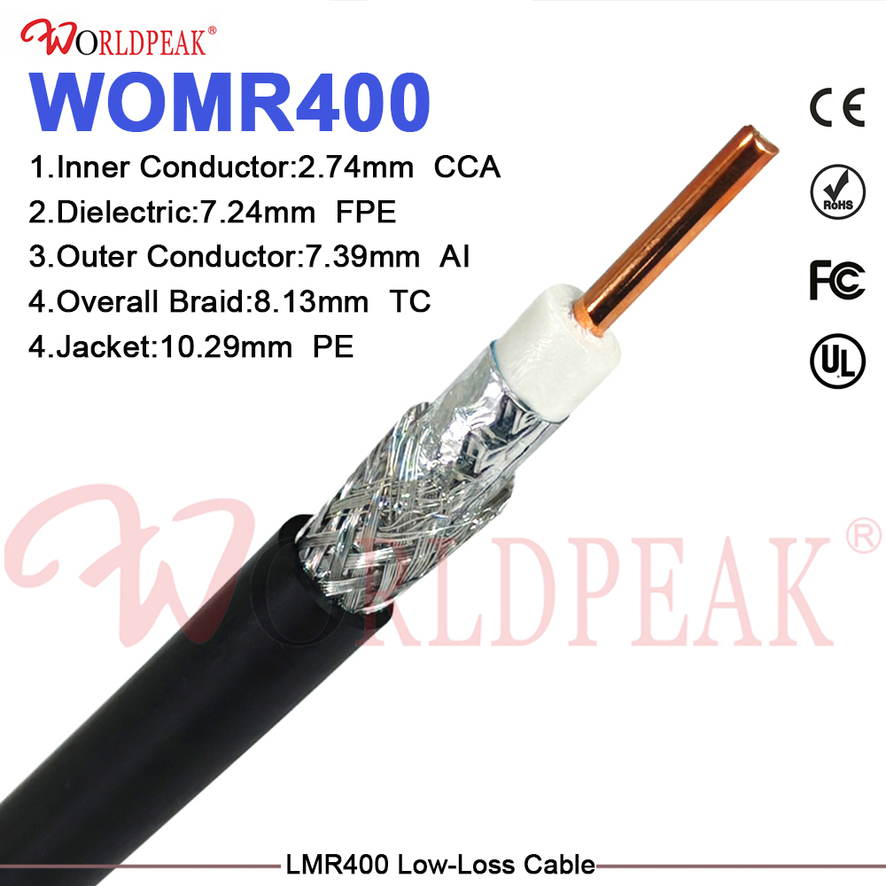
For procurement teams sourcing LMR400 Low-Loss 50 Ohm Coaxial Cable for base station feeder or wireless infrastructure projects, it is worth confirming that the connector assembly uses manufacturer-recommended termination hardware—the LMR series requires specific crimp or compression tools to achieve the rated insertion loss and weatherproofing performance at the connector interface.
AL400: Cost-Effective Alternative with Similar Loss Profile
AL400 is a direct functional equivalent to LMR-400 in terms of outer diameter (approximately 0.405 inches), impedance (50 ohms), and attenuation profile. The primary difference is construction: AL400 typically uses an aluminum foil outer conductor rather than the bonded aluminum of LMR, and the jacket compound may differ between manufacturers.
The insertion loss difference between a well-made AL400 and a standard LMR-400 is negligible for most practical infrastructure applications in the 400 MHz to 2.5 GHz range. Where differences appear is in long-term UV and environmental performance, connector termination consistency, and batch-to-batch electrical stability. If your application involves a controlled indoor environment or the cable is well-protected in conduit, AL400 can deliver equivalent electrical performance at a lower unit cost. For direct-burial or exposed outdoor runs, the material specification of the jacket and outer conductor becomes a meaningful reliability differentiator over a multi-year service life.
Belden 9913 and 9913F7: Established Performance Standards
Belden 9913 is a 50-ohm low loss coaxial cable that predates the LMR family and remains widely specified in amateur radio, professional audio RF, and legacy infrastructure applications. The 9913 uses a solid copper center conductor and a combination foil-plus-braid outer conductor, while the 9913F7 variant uses a stranded center conductor for improved flexibility.
The insertion loss of Belden 9913 is comparable to LMR-400 at VHF and lower UHF frequencies. At higher frequencies, the stranded center conductor of the 9913F7 introduces slightly higher resistive loss than the solid center of standard 9913 or LMR-400. For applications at 2.4 GHz and above, this difference—roughly 5% to 10% higher attenuation on the F7 variant—can matter in link budgets with thin margin.
Where Belden maintains an advantage is connector ecosystem depth and multi-vendor interoperability. For systems where a specific connector tooling set and supplier qualification is already locked in, Belden 9913 compatible termination hardware is available from a wide range of suppliers, which can reduce procurement lead time for accessories.
Attenuation Comparison at Key Frequencies
| Cable Type | Impedance | Loss at 900 MHz (dB/100ft) | Loss at 2.4 GHz (dB/100ft) | Center Conductor |
|---|---|---|---|---|
| LMR-400 | 50Ω | ~3.2 | ~5.6 | Solid copper |
| AL400 (typical) | 50Ω | ~3.4 | ~5.8 | Solid copper or CCA |
| Belden 9913 | 50Ω | ~3.1 | ~5.5 | Solid copper |
| Belden 9913F7 | 50Ω | ~3.4 | ~6.1 | Stranded copper |
These figures are approximate and should be verified against current manufacturer datasheets for your specific frequency plan. The insertion loss figure in the datasheet is a useful starting point—actually, it is more of a lower bound—because field-installed performance depends on how many connectors are in the chain and how they were terminated and torqued.
50Ω vs. 75Ω: Matching Impedance to Application
The comparison above covers only 50-ohm cables, which is the correct choice for professional RF transmission systems including base station feeders, ham radio installations, Wi-Fi infrastructure, and microwave cable runs for backhaul and point-to-point links. The 50-ohm standard optimizes the balance between power handling and signal loss for transmit-receive systems.
For video distribution, CCTV, and cable television infrastructure, the relevant standard is 75 ohms, where RG6 and its associated rg6 cable connectors (F-type, BNC 75-ohm) are the standard. RG59 siamese cable—combining RG59 coax with a power pair for camera power and signal in one sheath—is a common choice for analog CCTV installations where runs are shorter and low-loss performance is secondary to the convenience of a combined power-and-signal run.
If your application involves both RF transmission at 50 ohms and video distribution at 75 ohms, these are two distinct cable families with incompatible impedance characteristics. Mixing them in a signal chain without impedance matching introduces reflections that VSWR measurements will expose immediately.
Installation Considerations: Bend Radius and Connector Termination
Before specifying any low loss coaxial cable, confirm the minimum bend radius against your actual routing geometry. LMR-400 specifies a minimum one-time bend radius of approximately 1 inch and a minimum repeated bend radius of approximately 4 inches. For a microwave cable routing inside an equipment rack or through tight conduit bends, this means LMR-400 is manageable but not as forgiving as smaller-diameter cables. AL400 typically matches LMR-400's bend radius specification due to the similar outer diameter.
Connector choice must be matched to cable outer diameter and jacket material. Using non-manufacturer-recommended connector tools for LMR-type cables is one of the most consistent sources of elevated VSWR I've observed in field installations—the compression or crimp geometry is cable-specific, and an incorrectly terminated end introduces reflection that the cable itself would not cause.
Which Low-Loss Coaxial Cable Should You Choose?
If your primary constraint is outdoor environmental performance and frequency coverage through 5.8 GHz, LMR-400 offers the most proven combination of UV-stable jacketing, solid-conductor loss performance, and connector tooling availability. If your constraint is unit cost on high-volume infrastructure runs in a protected or indoor environment, AL400 provides comparable electrical performance at reduced cost, but qualify the supplier's jacket and outer conductor specification before committing to a large order. If your application is in the VHF to UHF range and you already have a Belden-compatible connector infrastructure, Belden 9913 remains a technically competitive option—just specify 9913 rather than 9913F7 if insertion loss at or above 2.4 GHz is a link budget factor.
There is no single universally superior low loss coaxial cable—the right choice depends on your frequency plan, installation environment, and the connector tooling you have already qualified. What matters most is making the decision with the attenuation figures, bend radius limits, and environmental ratings in front of you, not after the cable arrives on site.





