 EN
EN

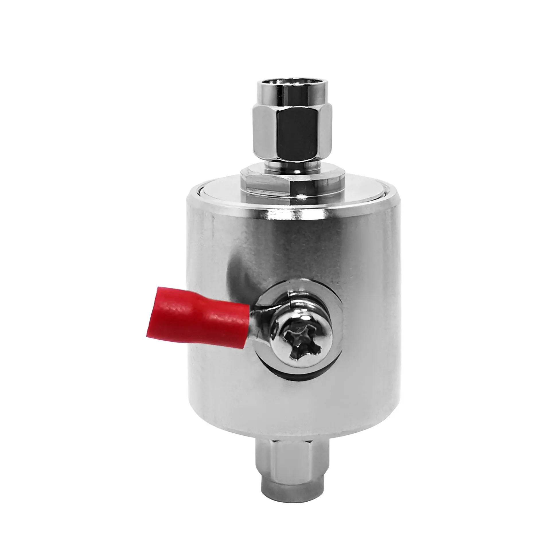
Male SMA Connector: RF System Integration Notes
A male SMA connector is a small part of an RF path, but it can influence the result of the whole assembly. In communications equipment, security systems, test benches, and industrial automation, a connector must do more than fit a cable: it must preserve the intended impedance, survive the installation environment, and mate consistently. As an RF systems engineer, I start by tracing the signal path rather than selecting a connector from its outline alone.
That distinction matters because a male SMA connector that appears suitable on a parts list can still create return-loss, stress, or reliability problems when the mating interface, cable, and enclosure are considered together. The same applies when teams compare an rp sma male interface, a ufl to sma connector assembly, or an external sma antenna connector.
Start with the RF job, not the connector family
SMA is a threaded 50-ohm coaxial interface widely used where compact size and repeatable RF performance are important. Many standard SMA series are specified through 18 GHz, while some precision variants are rated higher; the exact frequency limit belongs to the specific connector and cable assembly datasheet. That is the first boundary to set. A connector family name is not a guarantee of system bandwidth or power handling.
For each male SMA connector location, document four conditions: system impedance, highest operating frequency, expected power at that point, and the mechanical environment. Then add the less obvious variables: mating-cycle count, cable bend radius, vibration, moisture exposure, and access for a torque tool. Actually, those installation details often decide whether a laboratory-quality measurement remains stable after deployment.
Where SMA fits in communications, security, and automation
Communications equipment
Compact radios, antennas, filters, and RF modules often use SMA interfaces when panel space is limited and the signal path needs a threaded coupling. A male SMA connector can be a practical choice for short interconnects and removable antenna leads, provided the frequency, power, and cable flexibility are confirmed as one specification set. For outdoor equipment, environmental protection comes from the complete mated assembly and enclosure design, not from a connector label alone.
Security and video backhaul
In wireless security equipment, the sma antenna connector is usually part of a chain that includes the antenna, cable routing, and mounting hardware. A poorly supported cable can transfer motion into the connector interface. Use strain relief near the panel, avoid a sharp bend directly behind the termination, and verify that the chosen interface matches the antenna-side gender and polarity.
Industrial automation
Factory radio links and instrumentation may face vibration, dust, temperature cycling, and constrained cabinet layouts. Here, connector selection is conditional: if vibration or repeated servicing is expected, specify the mounting and cable support scheme before choosing a convenient adapter. A compact SMA connection is useful only when the mating condition remains controlled.
SMA, N, BNC, and TNC: choose by constraints
| Interface | Typical selection role | Coupling style | Decision question |
|---|---|---|---|
| SMA | Compact RF modules, antennas, and higher-frequency interconnects | Threaded | Do you need a small 50-ohm interface with controlled mating? |
| N type | Larger antenna and infrastructure connections | Threaded | Is a more robust, larger-format interface appropriate for the installation? |
| BNC | Quick-connect test, video, and lower-frequency work | Bayonet | Is fast connection more important than a threaded coupling? |
| TNC | Threaded applications needing vibration resistance | Threaded | Does the environment favor a threaded alternative to BNC? |
These are selection roles, not universal performance claims. Frequency and power limits vary by series, material, cable, and termination method. If frequency headroom is the primary constraint, compare the published assembly ratings. If field handling is the primary constraint, compare coupling, sealing strategy, cable support, and service access.
Check polarity and transitions before purchasing
One common source of integration delay is treating an rp sma male connector as interchangeable with standard SMA. Reverse-polarity SMA changes the contact arrangement while retaining a similar threaded outer geometry. Confirm the interface definition on both mating parts rather than relying on a product photo or a generic “male” description.
A ufl to sma connector cable creates another transition that deserves attention. The board-side micro connector, cable diameter, routing path, and panel-side SMA termination all contribute to the RF and mechanical result. Keep the cable as short as the layout allows, respect the manufacturer’s bend guidance, and secure the cable so that normal servicing does not pull on the board connector.
Practical installation and verification steps
- Confirm 50-ohm compatibility across the connector, cable, antenna, and instrument port.
- Inspect threads and center contacts before mating; do not force a cross-threaded coupling.
- Use the torque value specified for the particular connector series and tool; over-tightening can damage the interface.
- Support the cable and maintain bend radius so the connector is not used as a load-bearing point.
- After installation, verify continuity and insulation as appropriate, then measure return loss or VSWR across the operating band when the system is performance-critical.
For applications requiring a verified product starting point, review the published details for the RF-PRO-SMA-50M SMA Connector or the RFX-Custom-01 SMA-Male to MCX-Female RF Connector. Treat their published specifications as product-specific inputs to your own system review.
Final selection checklist
Choose a male SMA connector only after the interface, impedance, frequency, power, mounting method, and exposure conditions agree with the complete RF path. There is no universally preferred connector family for every installation. For a compact indoor module, SMA may be the appropriate balance. For a larger outdoor antenna run, another interface and enclosure strategy may be more suitable. The disciplined approach is simple: define the electrical boundary, control the mechanical installation, and verify the assembled path rather than the connector in isolation.





