 EN
EN

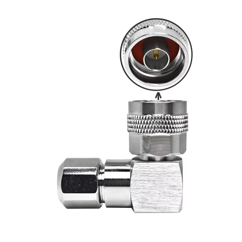
Subminiature and miniature coaxial interfaces often struggle when microwave installations transition into high-power broadcast runs, rooftop cell sites, and ruggedized industrial conduits. The type n connector remains the primary threaded 50-ohm interface for field installations requiring high mechanical endurance, consistent microwave impedance, and dependable environmental protection. Originally developed to support military radio communications up to 11 GHz, modern precision iterations of the n connector operate comfortably up to 18 GHz while handling substantial RF power.
Procuring the correct n connector requires matching physical cable dimensions, panel sealing requirements, and microwave frequency limits to the exact operational environment. Understanding structural trade-offs prevents field rework, signal reflection, and premature mechanical failure.
Mechanical Architecture and Critical Impedance Hazards
The type n connector relies on an air-dielectric interface coupled with a 5/8-24 UNEF screw thread mechanism. This threaded outer ring allows installers to apply repeatable mating torque without the mechanical play typical of bayonet connections. Industry manufacturing adheres to specifications governed by IEC 61169-16 and MIL-STD-348, defining exact interface dimensions and pin depths.
A critical engineering hazard involves confusing 50-ohm and 75-ohm variants. While both feature identical 5/8-24 coupling threads, their internal pin geometries differ drastically. Mating a 50-ohm male pin into a 75-ohm female contact permanently deforms the smaller 75-ohm spring basket, destroying the connector.
Mechanical Feature
50-Ohm Type N Connector
75-Ohm Type N Connector
Engineering Impact
Center Conductor Diameter
Approximately 1.60 mm
Approximately 0.70 mm
Intermating causes permanent destruction of 75-ohm contacts
Inner Dielectric Profile
Air dielectric at mating plane
Extended PTFE dielectric
Controls characteristic impedance and cutoff frequency
Frequency Ceiling
Up to 11 GHz (precision to 18 GHz)
Up to 2 GHz or 3 GHz
Mismatched impedance causes high reflection coefficients
Primary Usage
Wireless telecom, radar, aerospace
Cable TV, legacy broadcast, video feeds
Incorrect procurement degrades link return loss
| Mechanical Feature | 50-Ohm Type N Connector | 75-Ohm Type N Connector | Engineering Impact |
|---|---|---|---|
| Center Conductor Diameter | Approximately 1.60 mm | Approximately 0.70 mm | Intermating causes permanent destruction of 75-ohm contacts |
| Inner Dielectric Profile | Air dielectric at mating plane | Extended PTFE dielectric | Controls characteristic impedance and cutoff frequency |
| Frequency Ceiling | Up to 11 GHz (precision to 18 GHz) | Up to 2 GHz or 3 GHz | Mismatched impedance causes high reflection coefficients |
| Primary Usage | Wireless telecom, radar, aerospace | Cable TV, legacy broadcast, video feeds | Incorrect procurement degrades link return loss |
RF Interface Selection Across Common Coaxial Families
Selecting an n connector requires evaluating overall enclosure footprint, maximum operating frequency, power dissipation, and expected mating cycles. Compared to compact subminiature options, the larger footprint of the type n connector delivers structural rigidity and superior power handling.
Interface Family
Coupling Mechanism
Upper Frequency Limit
Power Capability at 1 GHz
Typical Failure Mode in Field Deployments
Type N Connector
5/8-24 Threaded
Up to 18 GHz
~1000 W
Thread galling from overtightening or improper alignment
SMA Connector
1/4-36 Threaded
Up to 26.5 GHz
~100 W
Stripped miniature threads and damaged center pins
BNC Connector
2-Lug Bayonet
Up to 4 GHz
~100 W
Intermittent contact under vibration and weather ingress
TNC Connector
7/16-28 Threaded
Up to 11 GHz
~300 W
Dielectric displacement during rough cable installation
4.3-10 Connector
Threaded / Quick-Lock
Up to 12 GHz
~500 W
Inadequate torque or contamination on radial mating surfaces
| Interface Family | Coupling Mechanism | Upper Frequency Limit | Power Capability at 1 GHz | Typical Failure Mode in Field Deployments |
|---|---|---|---|---|
| Type N Connector | 5/8-24 Threaded | Up to 18 GHz | ~1000 W | Thread galling from overtightening or improper alignment |
| SMA Connector | 1/4-36 Threaded | Up to 26.5 GHz | ~100 W | Stripped miniature threads and damaged center pins |
| BNC Connector | 2-Lug Bayonet | Up to 4 GHz | ~100 W | Intermittent contact under vibration and weather ingress |
| TNC Connector | 7/16-28 Threaded | Up to 11 GHz | ~300 W | Dielectric displacement during rough cable installation |
| 4.3-10 Connector | Threaded / Quick-Lock | Up to 12 GHz | ~500 W | Inadequate torque or contamination on radial mating surfaces |
Terminating Low-Loss Jumper Lines with LMR 400 Hardware
Low-loss solid-core cables are industry standards for routing microwave signals from radio units to external antennas. Terminating these heavy-shielded cables requires a dedicated lmr 400 n type male connector designed specifically for 10.29 mm outer diameter coaxial geometry.
Because LMR-400 uses an aluminum foil wrap combined with a tinned copper braid and a solid or stranded copper-clad aluminum center conductor, an lmr 400 n type male connector must provide both a secure mechanical shield grip and a stable central contact. Installers can select between solder-pin designs or fully crimped pins, provided the proper strip dimensions are maintained.
Assembly Step
Solder-Type LMR 400 N Type Male Connector
Crimp-Type LMR 400 N Type Male Connector
Quality Control Check
Center Pin Attachment
Heat pin pocket with 60W iron; flow 60/40 or SAC305
Crimp using precision 0.100-inch (2.54 mm) hex die
Verify zero solder flash on pin exterior or indent distortion
Braid and Foil Seating
Comb braid evenly over tapered ferrule shoulder
Slip ferrule over outer braid without crushing inner dielectric
Check that aluminum foil does not tear or bunch backward
Outer Ferrule Crimping
Crimp outer sleeve with 0.429-inch (10.90 mm) hex die
Crimp outer sleeve with 0.429-inch (10.90 mm) hex die
Inspect ferrule for symmetric hexagonal compression
Strain Relief Installation
Heat-shrink adhesive-lined polyolefin boot over joint
Heat-shrink adhesive-lined polyolefin boot over joint
Confirm 360-degree adhesive bead flows at jacket overlap
| Assembly Step | Solder-Type LMR 400 N Type Male Connector | Crimp-Type LMR 400 N Type Male Connector | Quality Control Check |
|---|---|---|---|
| Center Pin Attachment | Heat pin pocket with 60W iron; flow 60/40 or SAC305 | Crimp using precision 0.100-inch (2.54 mm) hex die | Verify zero solder flash on pin exterior or indent distortion |
| Braid and Foil Seating | Comb braid evenly over tapered ferrule shoulder | Slip ferrule over outer braid without crushing inner dielectric | Check that aluminum foil does not tear or bunch backward |
| Outer Ferrule Crimping | Crimp outer sleeve with 0.429-inch (10.90 mm) hex die | Crimp outer sleeve with 0.429-inch (10.90 mm) hex die | Inspect ferrule for symmetric hexagonal compression |
| Strain Relief Installation | Heat-shrink adhesive-lined polyolefin boot over joint | Heat-shrink adhesive-lined polyolefin boot over joint | Confirm 360-degree adhesive bead flows at jacket overlap |
Cabinet Penetrations and Bulkhead Sealing Protocols
When routing an antenna feeder line through an aluminum enclosure or stainless steel utility cabinet, a type n bulkhead connector provides the critical barrier between interior electronics and external moisture. Selecting a type n bulkhead connector requires matching the threaded rear barrel length to the cabinet wall thickness, including any gasket compression allowance.
A quality type n bulkhead connector incorporates an integrated silicone or fluorosilicone O-ring behind the front mounting flange, along with a rear lock washer and hex mounting nut. For pressurized or harsh chemical environments, hermetically sealed versions utilize glass-to-metal seals to prevent gas exchange along the center pin path.
Engineering Parameter
Standard Type N Bulkhead Connector
Hermetic Type N Bulkhead Connector
Procurement Guideline
Panel Ingress Rating
IP67 mated or capped
IP68 / True hermetic seal (
<10−8
mbar·l/s)
Match cabinet rating to external precipitation level
Body Plating Options
Nickel plate or white bronze (Tri-metal)
Gold plated or passivated stainless steel
White bronze minimizes passive intermodulation (PIM)
Mounting Cutout Style
D-hole or double D-hole anti-rotation
Circular hole with external lock-pin hole
Anti-rotation cutouts prevent twisting during cable mating
Dielectric Retention
Captive center contact with mechanical staking
Glass bead sealed directly to outer metal shell
Captive pins resist high axial forces during heavy cable pulling
| Engineering Parameter | Standard Type N Bulkhead Connector | Hermetic Type N Bulkhead Connector | Procurement Guideline |
|---|---|---|---|
| Panel Ingress Rating | IP67 mated or capped |
IP68 / True hermetic seal (
<10−8
mbar·l/s)
|
Match cabinet rating to external precipitation level |
| Body Plating Options | Nickel plate or white bronze (Tri-metal) | Gold plated or passivated stainless steel | White bronze minimizes passive intermodulation (PIM) |
| Mounting Cutout Style | D-hole or double D-hole anti-rotation | Circular hole with external lock-pin hole | Anti-rotation cutouts prevent twisting during cable mating |
| Dielectric Retention | Captive center contact with mechanical staking | Glass bead sealed directly to outer metal shell | Captive pins resist high axial forces during heavy cable pulling |
Assembly Torque and Commissioning Verification
Consistent electrical performance from an n connector installation depends entirely on mechanical discipline during assembly and torque application. Hand-tightening creates microscopic air gaps that spike insertion loss, while over-tightening with adjustable wrenches distorts the internal mating plane and strips the brass threads.
Every field-installed lmr 400 n type male connector and enclosure-mounted type n bulkhead connector must be tightened using an industry-standard calibrated click-style torque wrench. Following physical connection, network sweep testing identifies internal structural flaws prior to system deployment.
Inspection Stage
Acceptance Criterion
Test Instrument
Corrective Action for Non-Compliance
Interface Tightening
0.7 to 1.1 N·m (6.2 to 9.7 in-lbs)
Calibrated 13/16-inch torque wrench
Loosen, inspect thread condition, and re-torque
VSWR Sweep
≤
1.15:1 from 100 MHz to 6 GHz
Handheld vector network analyzer
Recrimp loose outer ferrule or replace bent pin
Return Loss Baseline
≥
23 dB across operational band
Portable RF cable and antenna analyzer
Inspect connector mating plane for debris or crushed contact
Distance-to-Fault (DTF)
Smooth trace with no localized discontinuities
FMCW or pulsed reflectometer
Re-terminate cable end showing localized impedance dip
| Inspection Stage | Acceptance Criterion | Test Instrument | Corrective Action for Non-Compliance |
|---|---|---|---|
| Interface Tightening | 0.7 to 1.1 N·m (6.2 to 9.7 in-lbs) | Calibrated 13/16-inch torque wrench | Loosen, inspect thread condition, and re-torque |
| VSWR Sweep |
≤
1.15:1 from 100 MHz to 6 GHz
|
Handheld vector network analyzer | Recrimp loose outer ferrule or replace bent pin |
| Return Loss Baseline |
≥
23 dB across operational band
|
Portable RF cable and antenna analyzer | Inspect connector mating plane for debris or crushed contact |
| Distance-to-Fault (DTF) | Smooth trace with no localized discontinuities | FMCW or pulsed reflectometer | Re-terminate cable end showing localized impedance dip |
Precision Manufacturing and OEM Capabilities with Worldpeak
Deploying dependable RF links requires connectors built with micron-level mechanical tolerances, durable contact alloys, and proven weather resistance. Whether procuring an off-the-shelf lmr 400 n type male connector or engineering a custom type n bulkhead connector for outdoor communication enclosures, component quality directly dictates link availability.
Operating high-precision multi-axis CNC Swiss lathes, automated plating production lines, and comprehensive vector network analysis labs, Worldpeak engineers and manufactures complete families of high-frequency coaxial hardware. Worldpeak delivers 50-ohm and 75-ohm connectors, adapters, and custom cable assemblies featuring white bronze (tri-metal) plating for low PIM and superior salt-spray corrosion resistance. Supporting telecom carriers, defense contractors, and industrial IoT integrators worldwide, Worldpeak provides custom engineering, rapid OEM prototyping, and scalable volume production to satisfy exacting wireless transmission demands.
Technical Questions and Answers
Engineering Inquiry
Technical Explanation
Recommended Action
Can an lmr 400 n type male connector fit standard RG-8 or RG-213 cable?
While outer jacket diameters are similar (~10.3 mm), dielectric diameters and center conductor gauges differ slightly between LMR-400 and legacy RG-8.
Always confirm that pin pocket diameter and internal ferrule geometry match the specific cable brand and construction.
Why is white bronze preferred over nickel on a type n bulkhead connector?
Nickel is ferromagnetic and generates significant passive intermodulation (PIM) when exposed to multi-carrier high-power signals.
Specify white bronze (tri-metal) or silver plating on every n connector deployed in commercial cellular infrastructure.
What causes sudden return loss degradation on an outdoor type n connector?
The primary cause is moisture migration through unsealed coupling threads, followed by contact pin oxidation or dielectric cracking from overtightening.
Install adhesive-lined heat shrink or self-amalgamating weatherproofing boots over every outdoor n connector junction.
| Engineering Inquiry | Technical Explanation | Recommended Action |
|---|---|---|
| Can an lmr 400 n type male connector fit standard RG-8 or RG-213 cable? | While outer jacket diameters are similar (~10.3 mm), dielectric diameters and center conductor gauges differ slightly between LMR-400 and legacy RG-8. | Always confirm that pin pocket diameter and internal ferrule geometry match the specific cable brand and construction. |
| Why is white bronze preferred over nickel on a type n bulkhead connector? | Nickel is ferromagnetic and generates significant passive intermodulation (PIM) when exposed to multi-carrier high-power signals. | Specify white bronze (tri-metal) or silver plating on every n connector deployed in commercial cellular infrastructure. |
| What causes sudden return loss degradation on an outdoor type n connector? | The primary cause is moisture migration through unsealed coupling threads, followed by contact pin oxidation or dielectric cracking from overtightening. | Install adhesive-lined heat shrink or self-amalgamating weatherproofing boots over every outdoor n connector junction. |





