 EN
EN

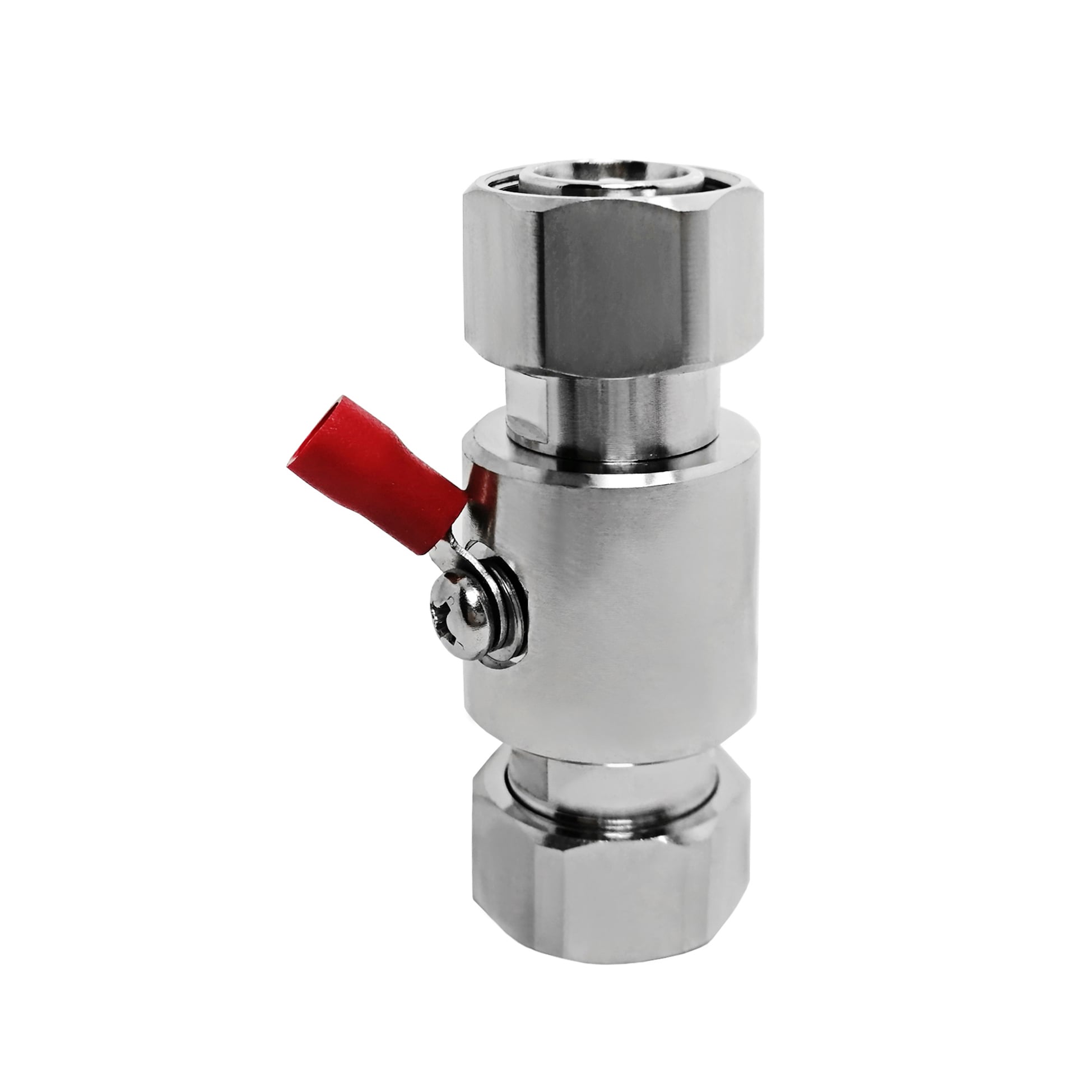
N Type to SMA: RF Adapter Specs and Compatibility
If you work with microwave test equipment, base station antennas, or outdoor RF installations, you have almost certainly run into a situation where you need to connect an N-type port to an SMA interface. These two connector families sit at different tiers of RF system design — N-type as the weatherproof workhorse for high-power outdoor links, and SMA as the compact high-frequency standard inside lab instruments and PCB-level assemblies. An n type to sma adapter handles that interface transition — but the configuration that works in a lab bench setup may not be the right call for an outdoor base station enclosure. Understanding the specs and physical differences helps avoid ordering errors and signal integrity problems down the line.
N-Type Connector: The RF Industry Baseline
The Type N connector was developed in the late 1940s and has stayed in active use across telecom, test, and defense RF systems ever since. Its threaded coupling, medium body size, and 50 Ω impedance made it the connector of choice for outdoor antenna systems, telecom base stations, cable television distribution equipment, and military RF assemblies. Standard N-type connectors are rated from DC to 11 GHz, though extended-range precision versions reach 18 GHz. The connector is specified under MIL-C-39012, which defines interchangeability across manufacturers — so an N-male from one vendor will mate cleanly with an N-female from another.
N-type connectors come in several physical variants that affect adapter selection:
- N-male (plug): The threaded outer shell closes around the female jack. Most cable assemblies use N-male at the cable end.
- N-female (jack): Found on antenna bases, splitters, and equipment panel ports.
- Right-angle N-type: Used where cable routing space is limited or where a 90° exit reduces mechanical strain on the connector body.
- Panel-mount N-type: Designed for bulkhead or chassis mounting, providing a through-wall RF feedthrough with a defined IP-rated seal.
SMA Connector: Compact High-Frequency Interface
SMA (Sub-Miniature version A) connectors share the same 50 Ω characteristic impedance as N-type, which means an n type to sma adapter is electrically transparent at the impedance level — no impedance mismatch is introduced at the transition. Where SMA distinguishes itself is frequency range and size. Standard SMA connectors are rated DC to 18 GHz, with some precision variants reaching 26.5 GHz. That extended upper frequency limit makes SMA the default choice inside spectrum analyzers, vector network analyzers, signal generators, and high-frequency PCB assemblies where N-type would simply be too large.
The SMA connector's threaded coupling (a 1/4-28 UNF thread) provides secure, vibration-resistant mating — important when test cables are connected and disconnected repeatedly. SMA also supports right-angle, panel-mount, and edge-mount PCB variants, mirroring the N-type form-factor options.
N-Type vs SMA vs TNC vs BNC: Where the Frequency Boundaries Fall
Choosing the right inter-series adapter means understanding what you can and cannot substitute. The table below captures the essential parameters:
| Connector | Impedance | Frequency Range | Coupling | Typical Use |
|---|---|---|---|---|
| N-type | 50 Ω | DC–11 GHz (up to 18 GHz extended) | Threaded | Outdoor antennas, base stations, high-power RF |
| SMA | 50 Ω | DC–18 GHz (up to 26.5 GHz precision) | Threaded | Lab instruments, PCB assemblies, test cables |
| TNC | 50 Ω | DC–11 GHz | Threaded | Mobile platforms, avionics, vibration-prone environments |
| BNC | 50 Ω / 75 Ω | DC–4 GHz | Bayonet | Video, oscilloscopes, general lab below 4 GHz |
N-type and TNC share the same 11 GHz upper boundary (in standard versions) and the same 50 Ω impedance, but they are not pin-compatible — TNC has a threaded outer and a smaller body than N-type. BNC's bayonet lock and lower 4 GHz ceiling make it unsuitable for most N-to-SMA applications; if you are working above 4 GHz, BNC is not a viable midpoint adapter.
So what does all that mean when you are sourcing an n connector to sma adapter for a base station maintenance job? At frequencies below 11 GHz, either connector type can handle the signal with minimal loss. Above 11 GHz — for example, connecting a 15 GHz test port to an N-type antenna port — the N-type becomes the bandwidth constraint, and you may need to stay within SMA-to-SMA connections for that portion of the signal path.
Practical Use Cases for N Type to SMA Adapters and Cables
The most common scenario for an n type to sma cable is bench testing: an antenna or amplifier module uses an N-type port (due to its weatherproof construction or high-power rating), while the test instrument — a spectrum analyzer, signal generator, or network analyzer — uses SMA ports. A short, precision-machined adapter or a quality cable assembly bridges the two interfaces without introducing significant insertion loss or VSWR degradation.
Outdoor deployments bring a second set of requirements. N-type connectors were designed with outdoor exposure in mind; many versions carry IP67 weatherproofing out of the box, making them resistant to dust ingress and temporary water immersion. If you need a sma to n type cable for an outdoor antenna application, the SMA end is typically protected inside a weatherproof enclosure or positioned at an equipment rack port, while the N-type end faces the antenna or feedline — exposed to weather, temperature cycling, and UV exposure.
For high-power applications — typical in broadcast transmitters, cellular base station combiners, or RF testing at elevated power levels — N-type handles power better than SMA. The larger contact area and geometry of the N-type connector distribute heat more effectively. An n type to sma cable used in these scenarios should specify insertion loss, maximum power rating, and VSWR at the operating frequency — not just the connector type and gender.
Impedance Matching: Why N-to-SMA Is a True Transparent Interface
Because both N-type and SMA share a 50 Ω characteristic impedance, an N-to-SMA adapter introduces no impedance transformation at the junction. Compare that to connecting a 75 Ω BNC video coax to a 50 Ω SMA port: that junction creates a mismatch that degrades signal integrity. With N-to-SMA, as long as you select an adapter with low insertion loss and good return loss across your operating band, the transition is essentially invisible to the signal.
Precision adapters for demanding test environments specify VSWR of 1.2:1 or better up to 18 GHz, and insertion loss below 0.15 dB at 10 GHz. Standard-grade adapters suitable for field work typically run 1.3:1 VSWR at the N-type frequency ceiling, which is within MIL-C-39012 specification.
For procurement engineers specifying sma to n type cable assemblies, the key parameters to confirm are: frequency range (must cover your system's operating band), impedance (confirm 50 Ω on both ends), VSWR budget across the operating band, IP rating if used outdoors, and body material for corrosion resistance. Stainless steel or gold-plated brass bodies are typical for environments with humidity, salt spray, or temperature extremes.
For SMA-side components in N-to-SMA cable assemblies, the RF-PRO-SMA-50M SMA Connector (50Ω, 0–18GHz, IP67, RoHS) covers the frequency range and environmental requirements typical of outdoor deployment scenarios. For OEM and ODM projects requiring custom inter-series adapter geometries, the RFX-Custom-01 Precision Machined RF Connector shows the machining tolerances and materials specification depth that inter-series work requires.
Selecting the Right N-to-SMA Configuration
Before ordering an adapter or cable assembly, resolve three questions:
- Gender at each end: Is the N-type port male or female? Is the SMA port male or female? Adapters are available in all four N-to-SMA gender combinations.
- In-line adapter vs. cable assembly: A rigid in-line adapter is compact and minimizes insertion loss but stresses the connector threads if connectors are misaligned. An n type to sma cable with a flexible or semi-rigid cable section absorbs mechanical offset and is preferred when frequent connect/disconnect cycles are expected.
- Operating environment: Indoor lab or bench work requires less protection than an outdoor installation in a coastal or industrial environment. Confirm IP rating, body material, and plating type before specifying for field use.
The N-type connector's status as an RF industry standard is unlikely to change anytime soon — too much installed infrastructure depends on it. For engineers and procurement buyers navigating N-to-SMA transitions, the combination of matched impedance, straightforward gender and configuration selection, and well-established component availability makes this one of the more predictable inter-series interface problems in RF system design.





