 EN
EN


Outdoor Coaxial Cable: UV-Resistant RF Cable Guide
As an RF systems engineer who has designed antenna feeder deployments across multiple climate zones, I've learned that choosing the right outdoor coaxial cable involves far more than picking the lowest-loss option from a datasheet. The installation environment—UV exposure, temperature swing, moisture ingress, and mechanical stress at bends. These set constraints that the electrical specs alone cannot resolve.
This guide breaks down what actually drives outdoor coaxial cable selection: structural materials, impedance, attenuation, shielding, and cable type trade-offs. Whether you're sourcing a LMR400 coaxial cable for a base station feeder run or evaluating flexible options for a compact antenna mount, understanding these parameters helps match the cable to deployment conditions before placing the order.
Understanding the Structure of an Outdoor Coaxial Cable
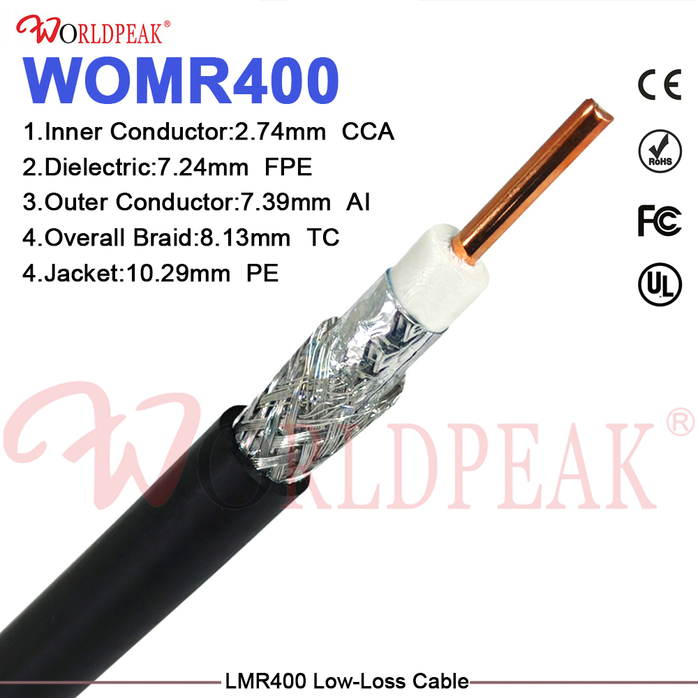
A coaxial cable has four layers: the center conductor, the dielectric insulation, the outer conductor (shield), and the jacket. For outdoor use, each layer carries specific performance implications:
- Center conductor: Solid copper is preferred over copper-clad steel for RF applications requiring low resistance, particularly at lower frequencies where conductor skin depth is larger.
- Dielectric: Foam polyethylene (PE) reduces insertion loss compared to solid PE and performs better across a wide temperature range. Solid PTFE dielectric is used in high-temperature or precision applications.
- Outer conductor (shielding): A bonded aluminum foil combined with a copper braid provides near-100% shielding effectiveness. For outdoor coaxial cable, bonded foil construction prevents moisture from migrating between jacket and shield over time.
- Jacket: UV-resistant PE is the standard choice for outdoor use. It resists UV degradation and ozone cracking significantly better than standard PVC; a PE-jacketed cable can maintain jacket integrity outdoors for up to 20 years in direct sunlight exposure, versus 5 to 8 years for general-purpose PVC.
During a receiving inspection for a batch of outdoor cable assemblies, I noticed that jacket micro-cracks were not visible in the packaged state but became apparent when the cable was uncoiled and gently flexed. This pointed to low-temperature embrittlement in the jacket compound—exactly the kind of issue that only surfaces after the cable has been stored in an unheated warehouse over winter.
50Ω vs. 75Ω: Matching Impedance to the Application
Impedance is the foundational decision when selecting an outdoor coaxial cable for RF work. The two common standards serve different application domains:
| Impedance | Primary Use Cases | Typical Cable Types |
|---|---|---|
| 50Ω | Base station feeders, antenna systems, RF test equipment, military/industrial RF | LMR400, RG58/U, RG196, LMR195 |
| 75Ω | CATV, satellite TV, broadcast distribution, consumer video | RG6, RG11, RG59 |
If your primary constraint is signal integrity in a telecom or base station feeder run, a 50Ω outdoor coaxial cable should carry the most weight in your selection. There is no single ideal cable type for every application—the right choice depends on your system impedance and the frequency range you need to cover.
Using a 75Ω cable in a 50Ω system, or vice versa, creates a systematic impedance mismatch that shows up as elevated VSWR and reflected power at every connection point. For low-frequency applications below 100 MHz, the effect may be marginal; at 1 GHz and above, the penalty becomes operationally significant.
Cable Type Comparison: LMR400, RG58/U, and High-Frequency Options
Most search results for outdoor coaxial cable focus on consumer RG6 (75Ω) products for TV and satellite. For B2B buyers sourcing professional RF systems, the comparison differs.
LMR400 — Low-Loss Standard for Long Outdoor Runs
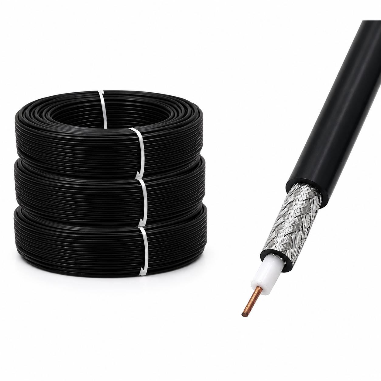
LMR400 is a 50Ω flexible cable with a foam PE dielectric, copper outer conductor braid, and UV-resistant PE jacket rated for continuous outdoor use. Its attenuation is roughly 3.9 dB/100ft at 1 GHz and 6.4 dB/100ft at 2.4 GHz—a ballpark estimate; actual performance depends on connector count and routing geometry. LMR400 is the preferred outdoor coaxial cable for feeder runs where loss budget is constrained, and a direct replacement for RG-8 and 9913-type cables. Worldpeak's LMR400 Low-Loss 50 Ohm Coaxial Cable covers outdoor base station and antenna feeder applications with this specification profile.
RG58/U — Lightweight Option for Shorter Runs
The rg58u cable is a 50Ω cable with a smaller outer diameter and higher attenuation per unit length than LMR400. It is practical for runs under 30 feet where the loss budget allows, or for flexible drop connections to test equipment and portable antenna systems. An rg58u cable with PE jacket is suitable for outdoor coaxial cable applications in benign environments, but its smaller outer conductor makes it more susceptible to mechanical damage in exposed installations. Outdoor deployments should specify PE-jacketed variants rather than standard PVC to maintain jacket integrity over multiple seasonal cycles.
RG196 and SMPM Interfaces — Precision and High-Frequency Applications
For applications extending above 26 GHz or requiring miniaturized RF interfaces, smpm cable assemblies are the appropriate choice. SMPM (also called GPO) connectors use a push-on mating mechanism and are available in 50Ω semi-rigid and flexible cable configurations. While smpm cable assemblies are primarily used in instrumentation and defense electronics rather than field feeder runs, understanding where the interface standard applies helps procurement teams avoid specifying the wrong connector family. Worldpeak's RG196 50-Ohm Coaxial Cable engineering reference covers specifications for precision 50Ω coaxial applications where tight dimensional tolerances matter.
SMA Terminations on Outdoor Coaxial Cable
Many outdoor coaxial cable assemblies for base station and antenna work are terminated with SMA connectors. A sma male cable pigtail or assembly is commonly specified for connecting antenna elements, inline amplifiers, and outdoor RF hardware with SMA-compatible ports. When specifying a sma male cable for outdoor use, check that the connector body material and plating are rated for the installation environment—stainless steel body with gold plating maintains performance better under humidity and salt air than standard brass body construction.
Installation Considerations: Bend Radius and UV Aging
I initially assumed the same cable selection approach applied equally to indoor instrument racks and outdoor vertical antenna mast runs. The distinction became clear when mechanical fatigue from wind-induced vibration showed that a cable adequate for static bench use actively creates intermittent contact risk in an exposed outdoor installation.
Key installation factors:
- Minimum bend radius: For LMR400, the minimum bend radius is typically 1 inch for installation and 4 inches for repeated flexing. Exceeding these limits at cable routing turns can cause outer conductor deformation and impedance discontinuity at the bend point. I once specified a semi-rigid cable for a routing that had a tight 90-degree turn without verifying the bend radius against the chassis geometry—the consequence was outer conductor micro-cracking that only became measurable after six months in service.
- UV aging: PE-jacketed outdoor coaxial cable maintains jacket integrity significantly longer than PVC under direct sunlight. If the installation uses cable ties or clamping hardware that compresses the jacket, inspect the contact points for stress whitening annually.
- Water ingress at connectors: The weakest weatherproofing point in an outdoor coaxial cable run is the connector interface, not the cable body. Self-amalgamating tape over the mating connector and cable entry point is standard practice for outdoor RF installations exposed to driving rain.
- Temperature range: Verify that both the cable jacket and the connector materials are rated for the installation site's temperature extremes—not just the ambient air temperature but the surface temperature on sun-exposed cable trays or antenna mast runs, which can exceed ambient by 20°C or more in direct sun.
Selecting the Right Outdoor Coaxial Cable: A Decision Summary
It is tempting to select the lowest-attenuation outdoor coaxial cable and assume installation details will work out—that holds for short indoor runs. For an outdoor deployment with UV exposure, temperature cycling, and mechanical vibration, I would look harder at jacket material, bend radius compliance, and connector weatherproofing before finalizing the order.
- If your application is a base station or antenna feeder run over 30 feet at 1–6 GHz, specify 50Ω LMR400 with a PE jacket as the baseline outdoor coaxial cable.
- If run length and loss budget allow RG58/U, specify PE-jacketed variants and verify bend radius at all routing turns.
- If your system operates above 26 GHz or uses SMPM interfaces, select the cable assembly to match—standard LMR400 connectors do not interface with SMPM ports without an adapter.
- If the installation is in a coastal or high-humidity environment, specify stainless steel body connectors on the outdoor coaxial cable assembly and use self-amalgamating tape at all mating interfaces.
Worldpeak produces outdoor coaxial cable assemblies and RF connector products for telecom, industrial, and base station applications. For specification confirmation or custom cable assembly requirements, technical pre-sales review is available to verify application fit before order placement.




