 EN
EN

What environmental resistance can be customized for OEM rf cable
2026/09/25
Customize an rf high frequency cable for temperature, moisture, corrosion, vibration, flexing, and OEM validation needs.
2026/09/01
Passive RF devices are the silent, hard-working backbone of every solid wireless setup. While active equipment gets most of the spotlight for generating and amplifying signals, passive components do the heavy lifting when it comes to guiding, split-testing, filtering, and terminating those same signals. Because they run entirely on the energy within the RF signal itself, picking the right passive components directly dictates whether your network runs smoothly or suffers from constant loss and interference.
Whether you are designing a high-power cellular base station, setting up test bench setups, or bridging commercial feeds to legacy hardware through an rf to rca setup, understanding how passive RF devices operate is non-negotiable for system engineers and procurement teams alike.
Every time an RF signal travels down a cable, passes through a junction, or gets filtered to strip out noise, it encounters passive components. Because these parts do not use external power, any signal degradation, impedance mismatch, or thermal loss they introduce is permanent.
Choosing high-spec active hardware will not fix a weak link in your passive layout. In fact, a single low-quality RF connector or an underrated cable run can trigger impedance reflections, degrade your System Operating Margin (SOM), or create severe Passive Intermodulation (PIM) issues that disrupt entire networks.
The primary job of transmission lines is getting signals from point A to point B with as little attenuation and signal distortion as possible. Different passive RF devices within this category serve distinct operational needs:
Flexible Cables (RG Series): Standard options like RG58 or RG223 work well for short jumpers, indoor equipment racks, and bench tests where flexibility matters more than ultra-low loss.
Low-Loss Peaked Cables (LMR Series): Options such as LMR400 or LMR600 feature foil shielding and closed-cell foam dielectrics, making them a go-to choice for longer feeder runs and outdoor wireless bridges.
Corrugated Hardline (Heliax): Heavy-duty 1/2-inch or 7/8-inch smooth or corrugated copper cables deliver superior shielding and ultra-low attenuation for high-power broadcast towers and cellular sites.
Semi-Rigid and Conformable Cables: RG402 and RG405 cables excel in microwave applications reaching up to 26 GHz or higher, offering unyielding RF shielding inside tight chassis assemblies.
An RF connector creates a seamless electrical bridge between cables and system modules. Maintaining impedance matching across these interfaces is essential to stop signal reflections in their tracks.
| Connector Family | Frequency Range | Key Characteristics | Typical Use Cases |
| SMA | DC to 18 GHz | Threaded coupling, compact form factor | Test gear, IoT modules, small antennas |
| N Type | DC to 18 GHz | Weatherproof, durable, medium power | Outdoor base stations, feeder cables |
| BNC | DC to 4 GHz | Quick-lock bayonet mechanism | Video systems, laboratory instrumentation |
| TNC | DC to 11 GHz | Threaded version of BNC, handles vibration | Avionics, military vehicles, marine RF |
| 7/16 DIN & 4.3-10 | DC to 7.5+ GHz | High power rating, extremely low PIM | Cellular infrastructure, DAS networks |
When bridging mismatched connector types, high-precision adapters preserve signal integrity and prevent mechanical wear on permanent ports.
Frequencies are crowded, making filters crucial passive RF devices for trimming away unwanted interference and out-of-band emissions:
Low-Pass Filters: Allow signals below a specific cutoff frequency to pass while blocking higher frequencies.
High-Pass Filters: Block lower-frequency interference while letting higher frequencies pass through cleanly.
Band-Pass Filters: Isolate a narrow, specific frequency window—essential for crowded receiver front-ends.
Band-Stop (Notch) Filters: Trap and eliminate single targeted frequencies, such as local broadcast interference.
Managing signal distribution across complex networks requires fine-grained power adjustment using passive components:
Attenuators step down signal levels by exact decibel increments (such as 3 dB, 10 dB, or 20 dB). They keep high incoming power from overloading sensitive receiver stages and help balance signal paths across test environments.
Power splitters divide an input signal evenly across multiple output ports. Directional couplers tap off a small, precise percentage of a signal path (e.g., -20 dB) for real-time monitoring and measurement without disturbing the main line.
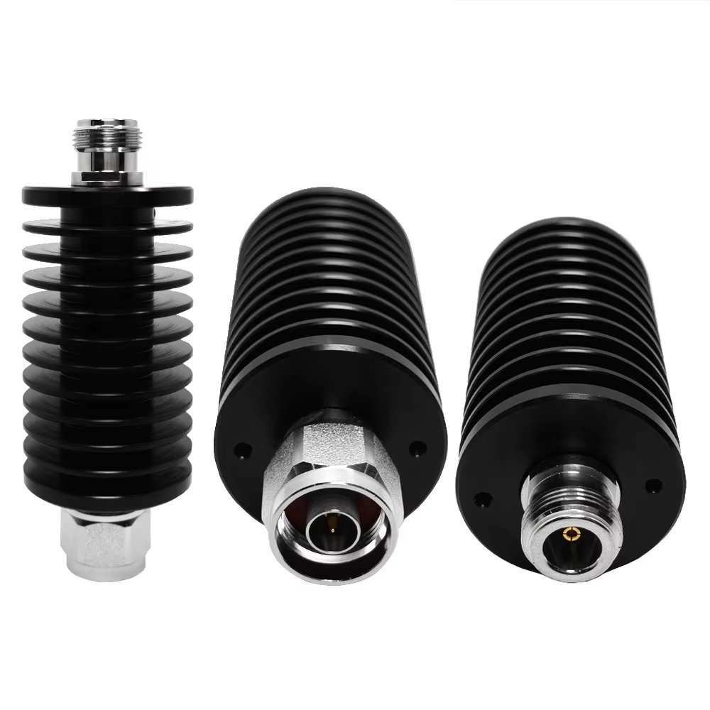
Leaving an open RF port invites signal reflections that bounce back through the system, creating standing waves (VSWR) and potentially damaging sensitive transmitters. RF terminations (or dummy loads) swallow unused RF energy cleanly and turn it into heat without reflecting power back down the line.
Not all systems run on standardized 50-ohm commercial RF infrastructure. Specialized interfaces, such as the rf to rca adapter, bridge the gap between high-frequency transmission feeds and consumer or legacy audio/video equipment.
An rf to rca interface takes a modulated RF signal from an antenna distribution unit or coaxial network and converts it into a clean signal compatible with standard RCA phono inputs. These passive adapters handle subtle impedance transitions and filter out extraneous line noise, ensuring steady audio and video distribution across multi-display installations, hotel networks, or retrofitted monitoring facilities.
To ensure top performance and long-term reliability from passive components, run through these selection criteria before finalizing your bill of materials:
Operational Frequency: Verify that every RF connector, filter, and cable is rated comfortably above your maximum operating frequency.
Power Capacity & VSWR: Ensure components can handle peak power output alongside potential reflected power from standing waves.
Impedance Alignment: Stick to consistent 50-ohm or 75-ohm signal paths to eliminate mismatch losses.
Environmental Shielding: For exposed setups, look for IP67 weather sealing, corrosion-resistant plating, and wide temperature tolerance.
Selecting reliable passive RF devices comes down to manufacturing precision, strict quality testing, and consistent material standards. Worldpeak supports global telecom operators, broadcast engineers, and system integrators with high-performance RF connector products, coaxial jumper assemblies, custom adapters, and passive components built for demanding environments. From standard RF connector fittings to custom passive RF devices, Worldpeak delivers the engineering quality and supply chain reliability your RF infrastructure requires.

2026/09/25
Customize an rf high frequency cable for temperature, moisture, corrosion, vibration, flexing, and OEM validation needs.

2026/09/25
Streamline RF equipment assembly lines with custom coaxial jumpers. Reduce line-side rework, ensure precise routing, and boost production efficiency.

2026/09/25
Learn PL-259 connector selection, soldering, weatherproofing, and RF applications for dependable antenna feedlines.

2026/09/25
Confirm impedance for a 90 degree coax connector with an ODM test plan covering VNA setup, VSWR, acceptance criteria, and release records.

2026/09/25
Learn when an n type coax connector can omit extra anti-corrosion treatment and when OEM exposure conditions require it.

2026/09/25
Learn how the custom cable and wire sample process helps ODM buyers validate design, testing, and production readiness.