 EN
EN

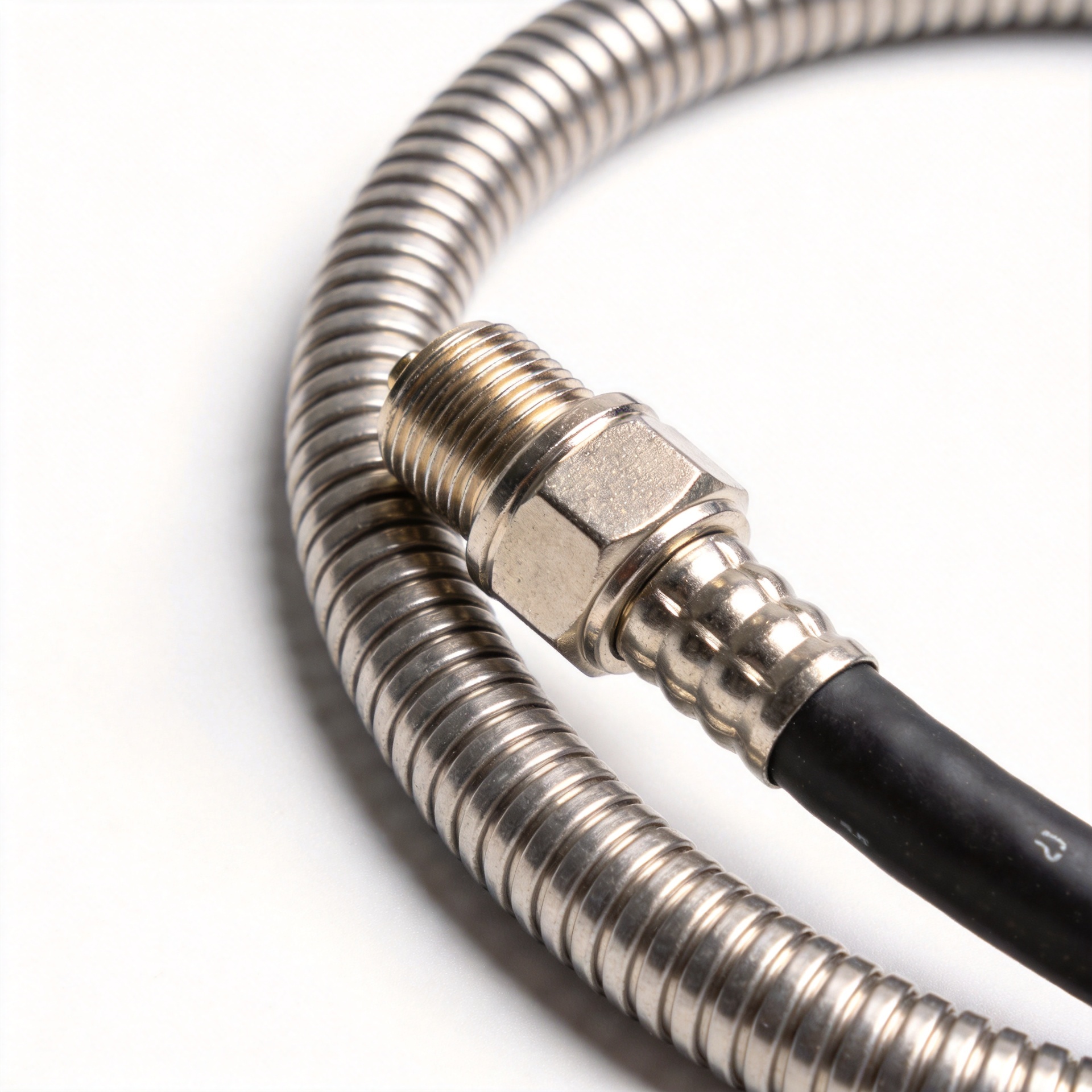
Replacing N Type RF Cable: When and How to Do It
In my experience, when a system that performed well at commissioning starts delivering degraded signal months later, the culprit is often the n type rf cable run—not the RF source or antenna, but the cable and its terminations. N-type connections are designed for long-term outdoor and industrial use, but they are not maintenance-free. Knowing when to replace an n type rf cable, and how to do it correctly, prevents signal problems from propagating across your entire system.
Signs That Your N Type RF Cable Needs Replacement
Before scheduling a replacement, verify that the cable is actually the source of the problem. The following symptoms, especially when they appear in combination, are reliable indicators that your n type rf cable has reached end of service life:
- Elevated VSWR readings: A healthy N-type connection should present a VSWR well within 1.5 at operating frequency. When measured VSWR climbs above this threshold—particularly at frequencies above 3 GHz—the connector interface or dielectric has likely degraded.
- Increased insertion loss: Datasheet insertion loss figures are a lower bound measured under controlled conditions. Actual field loss typically runs higher. If you are seeing insertion loss values that exceed your installation baseline by more than 0.5 dB at a given frequency, the cable is worth inspecting.
- Intermittent signal drops: Intermittency under vibration, thermal cycling, or wind loading typically points to a mechanical fault at the connector termination rather than bulk cable failure.
- Visible physical damage: Any kinking, crushing, jacket cracking, or moisture ingress at the connector entry point requires immediate replacement. Outer jacket damage that exposes the braid to environmental elements accelerates internal corrosion. Signal loss reaching 50% of expected transmitted power is a commonly cited threshold for mandatory replacement in outdoor coaxial runs.
- Connector body corrosion or contamination: Green or white oxidation on the N-type connector body, or visible contamination in the mating interface, indicates that the sealing has failed. Surface corrosion changes contact resistance and introduces dielectric loss that cannot be corrected by cleaning alone.
Why N Type RF Cables Fail: Common Root Causes
Before choosing a replacement, ask why the previous cable failed. Replacing the same cable type without addressing the root cause often results in repeat failure.
The most frequent causes of n type rf cable degradation in field installations are:
- Under-torqued or over-torqued connectors: N-type connector performance depends on the mating interface being tightened within specification. For stainless steel N-type bodies, the recommended torque range is 12 to 15 inch-pounds. Brass N-type bodies typically specify a lower range. Connections torqued by feel rather than by calibrated wrench often fall outside this window—either under-torqued and susceptible to micro-movement, or over-torqued and damaging the center contact or dielectric. This is one of the most common installation errors in the field, and it rarely shows up immediately; the connector performs acceptably at installation and degrades over subsequent thermal cycles.
- Bend radius violations at the cable entry: N-type cable assemblies are rated to a minimum bend radius determined by the cable type. Flexible cables like RG-58 and RG-8 have different minimum bend radii than semi-rigid or corrugated copper feeder cable. A cable forced into a bend tighter than its specification develops micro-fractures in the dielectric that do not appear as obvious outer jacket damage but cause increasing phase noise and insertion loss over time.
- Moisture ingress through connector boot failure: The rubber boot and sealing arrangement on outdoor N-type connectors degrade with UV exposure and thermal cycling. Once the sealing integrity is broken, moisture enters the connector body. Frequency response degradation from moisture-contaminated connectors reduces the effective contact area and introduces changes in the characteristic impedance that affect signal integrity.
How to Replace an N Type RF Cable: Step-by-Step Procedure
Once you have confirmed that replacement is necessary, the following procedure applies to standard field replacement of an n type rf cable with new cable and factory-terminated or field-terminated connectors.
- De-energize and lock out: Disconnect the RF source and verify that no signal is present on the cable before disconnecting any connectors. For base station feeder runs, coordinate with the network operations center before disconnecting.
- Document the existing installation: Photograph the cable routing, bend radii, and connector orientation before removal. This serves as a reference during re-installation.
- Remove the old cable carefully: Cut support ties rather than tearing them; aggressive cable removal can damage adjacent cable runs. Note the positions of support clamps and their spacing. Improper clamp spacing after replacement is a frequent cause of premature failure in new cable runs.
- Inspect the connector ports on the equipment: Before installing the new cable, check the N-type female ports on the antenna or radio unit for bent center pins, contamination, or corrosion. A new cable mated to a damaged port will fail at the equipment interface.
- Install the replacement cable with correct routing: Maintain the cable's specified minimum bend radius throughout the run. Use manufacturer-specified support clamp spacing, typically every 1 to 1.5 meters for 1/2-inch feeder cable on vertical runs. Ensure adequate drip loop before outdoor connector entries.
- Terminate and torque to specification: Connect the N-type connectors by hand until finger-tight, then apply torque with a calibrated torque wrench. For stainless steel N-type connectors, apply 12 to 15 inch-pounds. Do not substitute feel for measurement; the general rule is to torque to spec—with one practical exception being very short temporary connections for diagnostic purposes only, which should still be re-torqued for permanent installation.
- Apply weatherproofing: Use self-amalgamating tape followed by UV-resistant outer tape on all outdoor N-type connections. Begin wrapping from below the connector and work upward to direct water away from the mating interface.
- Verify performance after installation: Measure insertion loss and VSWR at the replaced cable segment before declaring the job complete. Measurements taken immediately after installation represent your new performance baseline for future comparison.
Choosing the Right Replacement Cable and Adapters
If the application requires transitioning between interface types at one end (for example, connecting an N-type feeder run to an SMA port on a radio unit), a quality adapter is more reliable than a re-terminated cable with a different connector type. A well-specified n male to sma male adapter rated for the operating frequency eliminates one termination point from the signal path while maintaining proper 50-ohm impedance matching. Similarly, for legacy CCTV or video distribution systems that use BNC interfaces, an n to bnc adapter allows a standard N-type cable run to interface with BNC-terminated equipment without splicing or re-termination.
For base station feeder applications that demand high power handling with low loss, a 1/2-inch corrugated copper feeder cable is the appropriate replacement choice for runs that require both mechanical robustness and low attenuation over long distances. The 1/2" Superflex Corrugated Copper Feeder Cable - 50 Ohm is one option for such applications, combining the flexibility advantages of superflex construction with the electrical performance of corrugated copper outer conductor design.
For applications where the connection point requires a high-power RF interface between a 7/16 DIN feeder system and an N-type equipment port, a properly rated adapter or transition connector may be appropriate. The RFX-Custom-02 High-Power RF Connector, 7/16 DIN Female to N Male is rated for 3 kW at 2.5 GHz and covers the 0–3.5 GHz range for high-power transmission system applications.
For distribution systems that use RG11 cable with F-type interfaces, note that the rg11 f connector termination torque and weatherproofing requirements differ from N-type. If your replacement run involves transitioning from RG11 to an N-type main feeder, verify that the adapter or in-line transition you select is rated for the combined insertion loss and power requirements of the system.
Post-Replacement Inspection and Documentation
The job is complete only after you have a written record of post-installation measurements: VSWR, insertion loss, applied torque values, weatherproofing method, and installation date. This baseline makes it possible to detect degradation at the next inspection rather than comparing against a datasheet specification that may not reflect the actual assembled performance.
Worldpeak specializes in RF connectors and coaxial cable assemblies, including pre-shipment electrical testing with insertion loss and VSWR sweep data supplied with each cable assembly shipment, giving replacement installers a verified incoming-inspection baseline rather than a nominal datasheet figure.





