 EN
EN

What environmental resistance can be customized for OEM rf cable
2026/09/25
Customize an rf high frequency cable for temperature, moisture, corrosion, vibration, flexing, and OEM validation needs.
2026/08/26
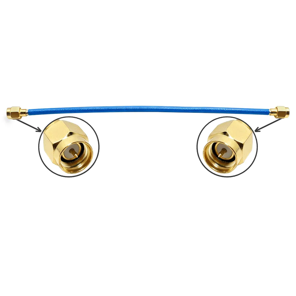
Choosing an RF connector is never just a minor administrative detail on a bill of materials; it is often the weakest link in your entire circuit design. Many engineering teams watch systems meet every electrical specification on paper only to see them fail in the field because the underlying coaxial connectors were selected for price alone. The right rf connectors, coaxial connectors, and coax connectors define your frequency ceiling, power handling limits, environmental resilience, and overall service life. This guide explores essential rf connector types, critical performance parameters, and a structured coaxial connector selection process designed for high-reliability applications.
Navigating the landscape of modern hardware requires knowing which interconnects fit specific applications.
SMA Interfaces: SMA connectors dominate module-level microwave designs, providing reliable performance up to 18 GHz.
BNC Interfaces: BNC hardware serves as the industry workhorse for standard test gear and video lines up to 4 GHz, available in both 50-ohm and 75-ohm variants.
N Type Interfaces: N type components offer rugged, threaded, and weatherproof performance up to 11 GHz with excellent high-power handling.
TNC Interfaces: TNC designs add robust vibration resistance to the standard BNC mechanical form factor.
U.FL and IPEX Options: U.FL and IPEX miniature options support ultra-compact internal wiring architectures up to 6 GHz.
Precision Lab Grades: Precision options like 3.5 mm and 2.92 mm extend laboratory measurements into the 26 to 40 GHz spectrum.
Four technical specifications dictate most engineering decisions when evaluating coaxial connectors. Impedance matching must align precisely with the system architecture, typically maintaining 50 ohms for pure radio frequency applications and 75 ohms for broadcast video. Frequency ratings establish the operational ceiling, and exceeding these limits quickly degrades voltage standing wave ratio (VSWR) and insertion loss. Power handling scales directly with physical size, contact materials, and frequency, meaning larger components naturally carry heavier loads. Environmental factors dictate plating types, such as gold for superior corrosion resistance and sealed housings for outdoor coax connectors. Mating durability—the count of connect-disconnect cycles a part tolerates—remains vital for field-service gear and test laboratories.
A disciplined, repeatable selection workflow prevents costly redesign loops.
Define Operating Parameters: Identify the target frequency band and maximum power level required by the active circuitry.
Select Impedance and Family: Choose the proper impedance and interface family that mechanically matches the source and load ports.
Determine Mechanical Form: Decide whether a plug, jack, panel, bulkhead, PCB mount, or right-angle orientation fits the enclosure layout.
Match Cable Dimensions: Coordinate the connector size precisely with the specific outer diameter and dielectric thickness of the transmission line.
Confirm Environmental Class: Specify indoor or outdoor exposure levels to dictate proper housing materials and protective plating.
Verify Standards Compliance: Check compatibility against military or industrial standards like MIL-STD-348 or IEC 60169 before finalizing procurement.
In a recent IoT gateway redesign, development teams initially specified premium SMA components across every internal and external port. A design review revealed that only the exterior cellular port required a user-serviceable interface, while internal paths could utilize more cost-effective internal coax connectors. This optimization reduced overall assembly costs significantly without impacting signal integrity. Conversely, another project suffered severe return loss degradation because a standard 4 GHz BNC link inadvertently carried a 5.8 GHz wireless signal. These scenarios underscore why a rigorous evaluation framework matters: choosing correct coaxial connectors on paper prevents expensive hardware recalls after product launch.
Engineering teams frequently stumble when mixing 50-ohm and 75-ohm components within the same signal path, which introduces severe reflections. Exceeding rated frequency limits, ignoring connector gender configurations, and deploying indoor-rated hardware in harsh outdoor environments remain frequent pitfalls. Mitigate these risks by explicitly documenting impedance values on schematics, verifying mechanical gender with mating diagrams, and prototyping with exact production-grade components tested via vector network analyzers.
Before mass production, quality assurance teams should audit incoming hardware shipments rigorously. Inspect surface plating carefully for uniform gold coverage on contact zones and clean, burr-free threads. Perform mechanical testing by mating and unmating sample pieces ten times to check torque consistency and center-pin retention forces. Measure electrical performance across the entire frequency band rather than a single spot frequency to ensure VSWR matches manufacturer datasheets. Verify crimp or solder dimensions against official tooling charts to prevent hidden termination failures, and always archive batch certificates for full traceability.
Securing reliable components at scale requires partnering with established manufacturers capable of handling complete vertical integration. Zhenjiang Worldpeak provides comprehensive engineering and volume production across extensive product lines, including BNC, SMA, N, TNC, and U.FL configurations within a vast portfolio backed by decades of specialized manufacturing experience. By utilizing strict batch-level testing protocols and rigorous quality management frameworks, industrial buyers can significantly minimize design risks and maintain consistent signal integrity across enterprise deployments.

2026/09/25
Customize an rf high frequency cable for temperature, moisture, corrosion, vibration, flexing, and OEM validation needs.

2026/09/25
Streamline RF equipment assembly lines with custom coaxial jumpers. Reduce line-side rework, ensure precise routing, and boost production efficiency.

2026/09/25
Learn PL-259 connector selection, soldering, weatherproofing, and RF applications for dependable antenna feedlines.

2026/09/25
Confirm impedance for a 90 degree coax connector with an ODM test plan covering VNA setup, VSWR, acceptance criteria, and release records.

2026/09/25
Learn when an n type coax connector can omit extra anti-corrosion treatment and when OEM exposure conditions require it.

2026/09/25
Learn how the custom cable and wire sample process helps ODM buyers validate design, testing, and production readiness.