RF armored wire: a special cable for high reliability signal transmission
2026/09/22
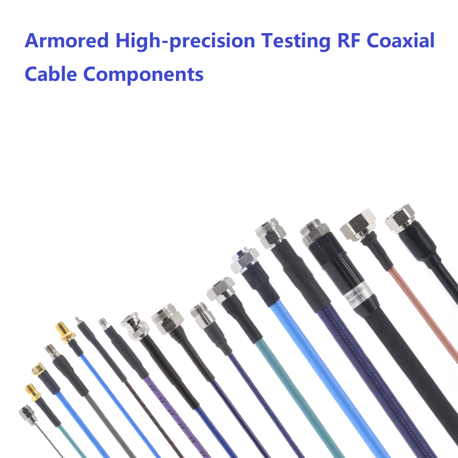
RF armored cable is a special type of cable that adds a high-strength steel wire braided or spiral wrapped armor protection layer on top of the standard RF coaxial cable. Its basic coaxial structure includes a central conductor, insulation medium, outer conductor shielding layer, and base sheath from the inside out. The outer metal armor is not used to optimize electrical performance, but to provide the ultimate physical protection capability for the cable.
The core advantages of these products are concentrated in the mechanical protection aspect:
Can resist severe compression, stretching, impact, and mechanical wear, avoiding damage to the internal precision coaxial structure
Form a hard physical barrier that effectively blocks rodent bites and damage in the wild and underground environment
As a load-bearing structure that shares longitudinal tension, it is suitable for high load scenarios such as vertical laying and long-distance overhead
High quality armor design can further enhance the overall shielding effect and reduce the impact of external electromagnetic interference
At present, mainstream commercial RF armored wires can cover an ultra wide frequency band of DC~110GHz. With different precision connectors, they can meet various high-frequency signal transmission needs from ordinary communication to high-end microwave testing.
Usage and application scenarios
The use of RF armor wire needs to be operated in accordance with the characteristics of the scene in order to maximize its protective value:
Conventional deployment: Confirm the minimum bending radius of the cable before laying to avoid forced bending that may cause deformation of the armor layer and discontinuous internal impedance; Use a standard torque wrench when connecting RF connectors to ensure connection reliability and repeatability.
High frequency testing scenario: When conducting precision VNA testing in the laboratory and interconnecting multi port testing fixtures on the production line, flexible phase stable armor models are preferred to reduce phase drift caused by frequent insertion and bending, ensuring consistency of test data.
Special environment deployment: When laying directly, wiring in mines/ports, and building field communication base stations, the compressive and tensile properties of the armor layer are utilized to resist soil pressure, vehicle crushing, and complex external force damage.
Its core application scenarios cover multiple areas with high reliability requirements:
RF microwave metrology calibration, high-end VNA testing and measurement scenarios
Extreme industrial environments such as mining exploration, port heavy industry, and field communication base stations
Wiring scenarios such as underground pipelines and storage areas that pose a risk of rodent damage
Large mobile communication devices, high dynamic mobile wiring scenarios inside robotic arms
Professional Selection Guide
When selecting, it is necessary to comprehensively judge from three dimensions: electrical performance, mechanical protection, and interface adaptation, in order to avoid performance redundancy or insufficient protection:
Frequency band and electrical specifications matching: Select the corresponding model based on the actual signal transmission frequency. For example, DC~6GHz low loss models can be selected for ordinary 6GHz testing scenarios, while stable phase armor components supporting DC~110GHz need to be selected for high-frequency precision testing above 70GHz. Simultaneously confirm that the characteristic impedance is uniformly 50 Ω and the shielding efficiency is ≥ 90dB, meeting the general standards for RF systems.
Armor type can be selected as needed: PVC armor can be selected for routine mild testing scenarios, with a compressive strength of 200N/25mm; For high-frequency plugging and heavy-duty environments, stainless steel PUR sheathed armor is selected, with a compressive strength of up to 1000N/25mm, greatly extending its service life.
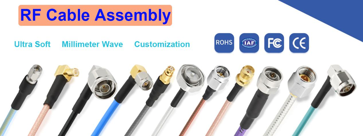
Interface and installation space adaptation: Select precision connectors such as Type N, SMA, 2.92mm, 1.85mm, etc. based on the port type of the docking device; For multi port intensive testing scenarios, small diameter and low rebound flexible armored cables are preferred to adapt to narrow installation spaces.
Key usage precautions
The overall weight and minimum bending radius of RF armored cables are greater than those of ordinary non armored cables. Sufficient turning space should be reserved during installation, and violent dragging and forced bending are prohibited to avoid deformation and damage to the internal coaxial structure of the armor layer.
During long-term use, it is necessary to avoid operating at over rated power to prevent the medium from overheating and aging, which may affect the stability of phase and amplitude.
When storing, it should be placed in a dry and ventilated environment to avoid long-term contact of the armor layer with corrosive liquids and prevent metal corrosion from reducing protective performance.
In high-frequency precision testing scenarios, it is recommended to regularly calibrate cable phase indicators to avoid performance drift after long-term repeated bending, which may affect the accuracy of test results
 EN
EN