 EN
EN

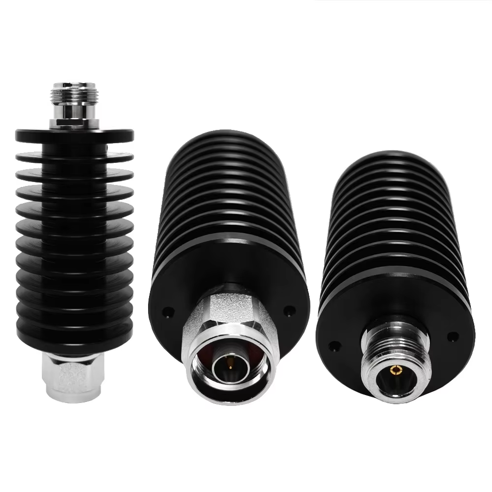
In high-frequency electronics and microwave systems, RF attenuators are frequently mistaken for simple inline pads. Yet these compact passive devices directly dictate whether a sensitive receiver operates within its linear dynamic range, a high-power solid-state amplifier survives a sudden impedance mismatch, or an automated laboratory calibration yields repeatable results. Selecting the right component goes far beyond picking a nominal decibel value off a catalog shelf. Sound engineering design demands evaluating frequency response, power handling, voltage standing wave ratio, connector integrity, and thermal dissipation across the complete signal path.
When an RF signal chain integrates wideband 5G arrays, high-power pulsed radar transmitters, or complex aerospace test racks, attenuation must be calculated in unison with surrounding passives such as an rf choke, directional couplers, or circulator rf isolation modules. Skimping on path-level balance or treating components as isolated blocks often leads to unexpected intermodulation distortion, thermal drift, or catastrophic hardware failure.
How RF Attenuators Stabilize Passive Signal Paths
At its primary functional level, an RF attenuator reduces signal amplitude by absorbing or reflecting a precise fraction of RF power while maintaining the system's characteristic impedance, typically 50 ohms or 75 ohms. A 10 dB attenuation value drops signal power by a factor of ten, leaving 10% of the input power transmitted while absorbing 90% as heat. A 20 dB pad reduces signal power by a factor of one hundred, transmitting only 1% of the input power and absorbing 99%.
Beyond basic signal amplitude reduction, attenuators perform vital system-level stabilization functions across modern RF signal chains:
-
Impedance Masking and Isolation: Placing a 3 dB or 6 dB fixed pad directly in front of a mismatched load or active stage dampens return loss by twice the pad's attenuation rating. For example, a 6 dB pad absorbs energy in both forward and reflected directions, delivering a 12 dB improvement in return loss. This effectively stabilizes sensitive gain stages and prevents local oscillator pulling.
-
Receiver Protection and Dynamic Range Expansion: Overdriven inputs in spectrum analyzers, power meters, or low-noise amplifiers risk permanent gain compression, intermodulation noise, or physical front-end burnout. Fixed rf attenuators establish a reliable power threshold, keeping active inputs safely within their linear operating window.
-
System Calibration and Reference Conditions: Precision pads create highly repeatable baseline power levels required for automated test equipment, laboratory sweep setups, and field equipment alignment.
An RF attenuator rarely works in isolation inside an active transceiver module or test manifold. In a typical front-end or bias injection network, an rf choke isolates direct current supply lines from high-frequency energy, preventing unwanted RF leakage into power rails. Meanwhile, high-frequency rf adapters connect mismatched transmission line families across chassis walls. Downstream, a circulator rf isolation unit directs dangerous reflected energy toward a dummy load. Treating these components as a single passive ecosystem prevents unwanted insertion losses, phase distortion, and thermal bottlenecks.
Selecting Fixed, Variable, and Programmable Types
Fixed Attenuators
Fixed rf attenuators deliver a permanent, unchangeable attenuation value such as 3 dB, 6 dB, 10 dB, 20 dB, or 30 dB. They excel in high-reliability production environments, cellular infrastructure links, and internal module pads where control lines and active switches would add unnecessary points of failure.
When evaluating fixed units, system integrators must look past nominal decibel values and analyze attenuation tolerance and frequency response flatness across the entire operating band. A component rated for 10 dB at 1 GHz might drift to 11.5 dB or higher at 6 GHz due to parasitic capacitance, substrate losses, and distributed line effects. Always review the Voltage Standing Wave Ratio at both ends of the band alongside the electrical quality of the mating connector interfaces.
Variable and Voltage-Controlled Attenuators
Variable units allow test engineers and system architects to adjust power levels dynamically during operational tuning, temperature compensation, or signal leveling. These fall into three primary technology categories:
-
Manual Step Attenuators: Calibrated mechanical switches housing multiple resistive pads inside a shielded enclosure, used heavily on microwave test benches for manual level sweeping.
-
Analog Voltage-Controlled Attenuators: Utilize PIN diodes or field-effect transistors to yield smooth, continuous attenuation changes driven by an analog control voltage. These are widely used in automatic level control loops.
-
Digital Programmed Attenuators: Driven by digital logic over SPI, I2C, or parallel interfaces, offering precise step sizes such as 0.25 dB or 0.5 dB steps up to 31.5 dB for automated test benches and smart transceiver beamforming arrays.
When selecting variable RF attenuators, pay close attention to minimum insertion loss. The baseline loss of internal solid-state switches and transmission line geometry can eat away precious link budget headroom, even when the variable attenuator is set to its 0 dB baseline state.
Power Handling and Thermal Dissipation Requirements
High-power RF attenuators do not merely block radio frequency signals; they convert excess electromagnetic energy directly into thermal dissipation. Underestimating thermal management is a leading cause of attenuator drift, dielectric degradation, and structural failure.
Average power specifications apply to continuous wave signals operating under specific ambient temperature conditions, usually benchmarked at 25 degrees Celsius. When operating in high-density equipment racks, remote radio units, or high-temperature defense enclosures, linear thermal power derating must be strictly applied according to manufacturer guidelines.
Pulsed RF applications present a different design challenge altogether. A pulsed radar transmitter might deliver 1 kilowatt of peak power, but if the duty cycle is only 0.1%, the calculated average power is just 1 Watt. While a standard 5-Watt attenuator might seem sufficient based on average power alone, the extreme peak voltage can exceed the dielectric breakdown threshold of the internal thin-film or thick-film resistive elements. Peak pulse voltage, pulse width, and duty cycle must always be calculated independently to prevent internal dielectric arcing and immediate component failure.
Integration Strategies Across Cascaded Subsystems
Optimizing a complete RF path requires strategic physical and electrical ordering of passive components. Placing an attenuator before or after a filter, multiplier, or amplifier stage completely alters the performance dynamics of the entire system:
-
Filter and Attenuator Sequence: Placing a fixed pad before a high-Q bandpass filter helps absorb out-of-band reflections, presenting a smooth 50-ohm match back to the preceding amplifier stage. Conversely, placing the filter first protects a delicate variable attenuator from high-level out-of-band harmonics generated by upstream power stages.
-
Protection via Circulator Isolation: In high-power transmitter output stages, a circulator rf device isolates the power amplifier from severe antenna mismatches. The reflected energy routed out of the circulator's secondary or tertiary port often passes through a high-power fixed attenuator before striking a power detector, ensuring safe monitoring levels for automatic shutdown logic.
-
Interconnect and Interface Matching: Every interface transition along a cable assembly introduces impedance discontinuities. Utilizing high-grade rf adapters with low VSWR prevents standing waves from creating destructive ripple patterns across the attenuation curve.
System-Level Selection Checklist for Integration
To streamline component procurement and system assembly, engineering teams should resolve these fundamental technical parameters prior to issuing a purchase order or finalizing a bill of materials:
-
Operating Bandwidth and System Impedance: Define the complete operational frequency range from lowest to highest frequencies, and confirm whether the signal path requires 50-ohm, 75-ohm, or custom line impedance.
-
Attenuation Value and Flatness Tolerance: Specify nominal decibel reduction, acceptable manufacturing tolerance limits, and maximum allowable attenuation drift over temperature and frequency.
-
Power Handling Dynamics: Calculate maximum continuous average power, peak pulse power, maximum pulse duration, duty cycle, and worst-case reverse power under open or short circuit fault conditions.
-
Physical Interface and Mounting Requirements: Select appropriate connector types, such as SMA, Type N, 2.92mm, 3.5mm, or 7/16 DIN, ensuring mating interfaces meet both power and frequency limits while matching physical mounting constraints.
-
Environmental and Mechanical Durability: Account for ambient operating temperatures, external heatsink airflow, mechanical shock, vibration exposure, corrosion resistance, and ingress protection levels.
End-to-End Interconnect Performance with Worldpeak
Building reliable high-frequency signal paths requires absolute electrical consistency across every single passive junction and transmission interface. A precision attenuator cannot deliver a flat frequency response or stable power handling if paired with low-grade coaxial jumpers, worn adapters, or high-VSWR interconnect hardware.
Worldpeak supports global microwave and communications integration with high-performance passive components, custom coaxial cable assemblies, precision adapters, and interconnect solutions built for 5G telecommunications infrastructure, defense electronics, aerospace applications, and laboratory testing environments. By maintaining rigorous manufacturing tolerances, advanced thermal engineering, and stringent quality control protocols, Worldpeak enables system designers to minimize unexpected insertion loss, eliminate thermal bottlenecks, and achieve predictable RF performance from signal source to antenna.





