 EN
EN

7/16 DIN Connector Guide: High-Power RF Standard
2026/09/24
Choose a 7 16 connector for high-power RF: compare DIN and Type N, protect PIM margin, and apply field installation checks.
2026/08/25
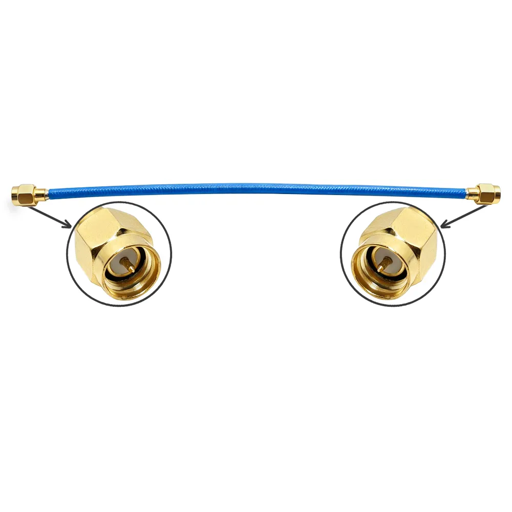
The RF BNC connector remains one of the most widely deployed coaxial interfaces globally. Developed back in the late 1940s, the bayonet-style BNC (Bayonet Neill-Concelman) design still reliably links antennas, radios, surveillance cameras, test instruments, and base-station equipment across various industries today. Experienced telecom and broadcast engineers quickly learn that selecting and installing a proper RF BNC connector often makes the critical difference between a stable, high-performance link and an urgent service call in the middle of the night. This comprehensive guide outlines the vital technical specifications, explores the common RF BNC connector types encountered on job sites, breaks down assembly methods, and reviews how strategic sourcing impacts overall project success.
Before choosing any RF BNC connector for an upcoming project, technicians and procurement teams must evaluate four core parameters: characteristic impedance, frequency range, mechanical coupling quality, and plating materials.
Most traditional RF BNC connector models are configured as 50 ohm types engineered specifically for telecom, data, and instrumentation hardware. Conversely, specialized 75 ohm BNC connectors serve video, digital audio, and professional broadcast systems. Mixing these two impedance standards creates severe reflection mismatches, leading to signal loss and transmission errors. Therefore, engineers must always match the connector impedance precisely to the coaxial cable and the broader system architecture.
A standard 50 ohm RF BNC connector typically rates up to approximately 4 GHz, perfectly covering cellular networks, Wi-Fi infrastructure, GPS applications, and general test-bench environments. While precision versions can extend performance slightly higher, 4 GHz remains a safe planning metric for practical procurement.
Mechanical quality is readily apparent in the bayonet locking mechanism. A superior-grade RF BNC connector features a firm 90-degree twist with a positive, secure lock, whereas substandard alternatives often wobble and develop intermittent contact over time. Procurement specialists should look closely for gold-plated center pins to maximize corrosion resistance, paired with durable brass or zinc bodies finished with nickel or tri-metal plating to balance overall cost and longevity in harsh environments.
The versatile RF BNC connector family encompasses plugs (male), jacks (female), panel mounts, bulkhead fixtures, PCB mounts, and a diverse array of adapters. The naming convention is straightforward: the male plug carries the central signal pin, the internal female socket receives that signal, and the outer bayonet sleeve belongs exclusively to the female side.
In everyday field deployment, technicians order RF BNC connector plugs for cable terminations, female receptacles for chassis and equipment panels, and reverse-polarity variants when specialized applications require non-standard interfaces to prevent mismatches. Interface dimensions strictly follow international specifications such as MIL-STD-348 and IEC 60169-8, ensuring that compliant parts from different manufacturers will mate seamlessly. Industry professionals always recommend sourcing components from established manufacturers capable of providing comprehensive dimensional and VSWR test reports, as mechanical tolerances at the mating interface are where quality issues frequently arise.
For rack-to-antenna jumpers, test-bench lab leads, and high-definition camera feeds, deploying a pre-fabricated bnc male to male cable often serves as the most efficient solution because both ends arrive ready for immediate connection. A factory-assembled bnc male to male cable is professionally terminated, rigorously tested, and fully documented right at the source, effectively eliminating the two most common field failure points: improper crimps and incorrect torque application.
During major broadcast facility upgrades, technical crews frequently replace dozens of hand-assembled patch leads with pre-built bnc male to male cables utilizing standard RG58 and RG174 coaxial sizes. This transition ensures consistent insertion-loss and VSWR readings across all transmission channels while significantly accelerating project completion times. For short indoor routing runs, an RG58-based bnc male to male cable balances overall cost, attenuation, and physical flexibility. Meanwhile, tighter equipment enclosures benefit from an RG174-based bnc male to male cable that routes smoothly despite slight increases in signal loss.
Three primary termination techniques dominate traditional RF BNC connector assembly: crimp, clamp, and solder styles.
The crimp approach stands out as the fastest and most repeatable method for high-volume production. Installers strip the coaxial cable to precise measurements, slide on the outer ferrule, position the center contact pin, and seal the connection using a calibrated crimp die.
Alternatively, clamp types utilize a mechanical compression sleeve requiring only standard hand tools like a wrench and a utility knife, making them exceptionally popular among field service crews handling emergency repairs.
Traditional solder termination still appears in high-vibration environments or ultra-short assembly configurations, though it demands a clean soldering iron and disciplined technician technique.
Regardless of the chosen method, technicians must follow the manufacturer's specified strip dimensions precisely. Many high-performance RF BNC connector parts fail prematurely simply because the internal dielectric insulation was cut too long or the braided shield wire was flared unevenly. Implementing a rigorous continuity and short-circuit test immediately following each assembly catches the vast majority of termination errors long before hardware reaches the field.
Across more than a decade of complex RF infrastructure projects, most system failures traced back to the BNC interface are entirely preventable. Common culprits include loose bayonet coupling nuts, mismatched 50 and 75 ohm components, and connectors improperly compressed with the wrong tooling die.
In maritime and coastal installations, aggressive salt spray can corrode unprotected connector bodies within a surprisingly short timeframe. Upgrading these vulnerable links to heavy-duty, gold-plated, weather-sealed RF BNC connector assemblies permanently eliminates recurring connectivity faults. The underlying lesson is clear: while individual components remain inexpensive, the unexpected downtime caused by inferior hardware carries a massive operational price tag. Selecting the proper impedance, choosing corrosion-resistant plating for challenging environments, and relying on pre-built jumpers when speed is paramount ensure long-term network stability.
When purchasing RF BNC connector hardware in high volumes, engineering managers must verify critical quality metrics, including complete batch traceability, detailed test documentation, and seamless manufacturing support for custom bnc connector types and ready-to-use cabling solutions.
Advanced manufacturing partners like Worldpeak bring decades of specialized RF production experience, extensive component inventories, and robust OEM/ODM assembly capabilities tailored for global telecom and broadcast customers. Working with a dedicated supplier capable of delivering both loose RF BNC connector components and fully tested bnc male to male cable assemblies with comprehensive factory test reports provides a distinct operational advantage. Strong supply-chain depth and strict quality control guarantee that critical infrastructure projects avoid costly delays, rework, and performance degradation in the field.

2026/09/24
Choose a 7 16 connector for high-power RF: compare DIN and Type N, protect PIM margin, and apply field installation checks.

2026/09/24
Compare TNC connector types, specs and applications, including RP-TNC, bulkhead options, vibration performance and adapter selection.

2026/09/24
Understand MMCX connector basics, RF limits, and how to choose the right coaxial interface for compact systems.

2026/09/24
Understand RP-SMA connector polarity, mating rules, frequency checks, and OEM termination options for reliable RF builds.

2026/09/24
Choose the right bnc male connector for RF, CCTV and test systems with clear 50Ω vs 75Ω, type and installation guidance.

2026/09/24
Compare LMR400 specs, cable loss, uses, connectors and RG8/RG213 alternatives with a practical RF loss-budget method.