 EN
EN

What environmental resistance can be customized for OEM rf cable
2026/09/25
Customize an rf high frequency cable for temperature, moisture, corrosion, vibration, flexing, and OEM validation needs.
2026/09/08
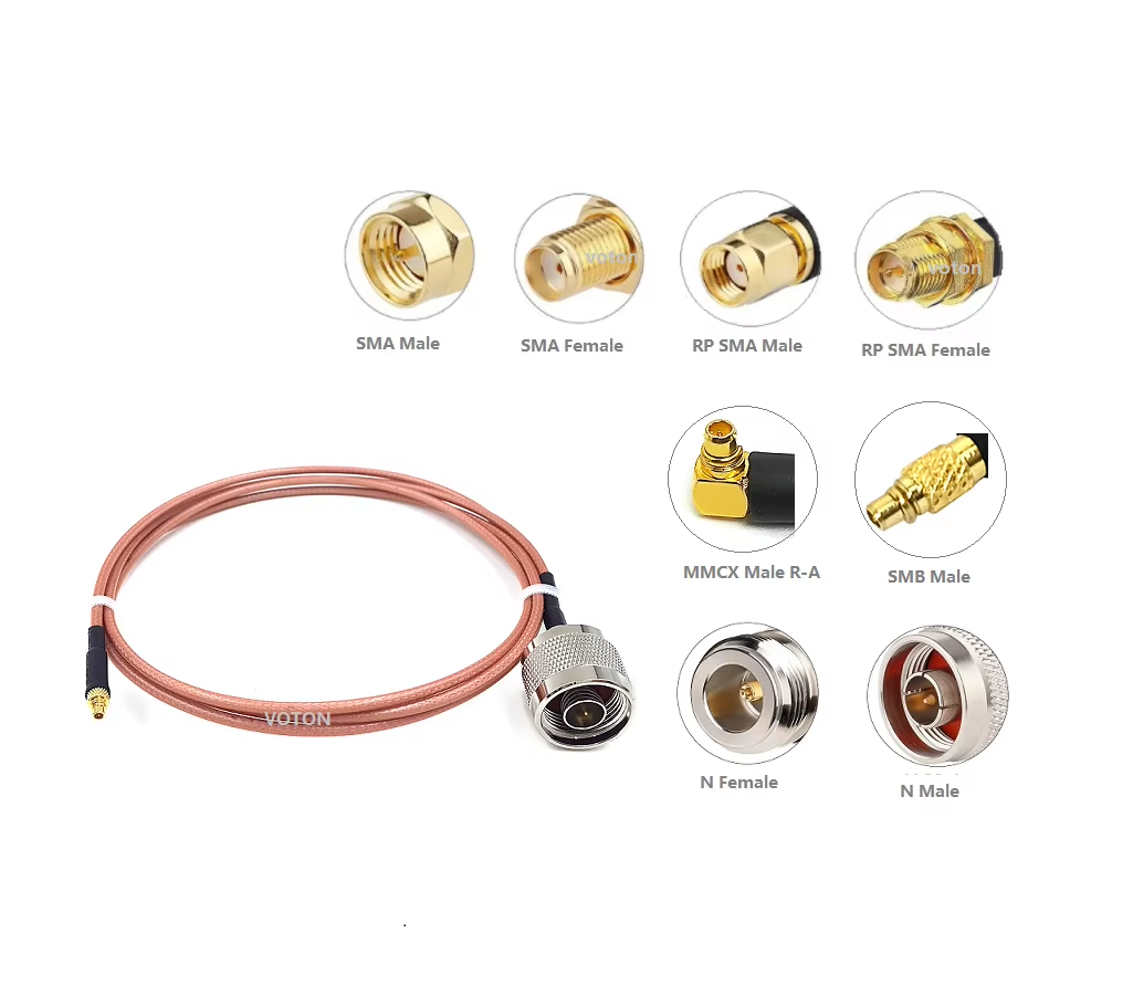
Selecting the right RF cable connector type represents one of the most critical decisions during wireless system architecture and hardware layout. An RF connector serves as more than a simple mechanical joint; it functions as an impedance-matched transmission path that determines maximum operating bandwidth, power handling capability, and structural reliability. Choosing an improper component leads to reflection loss, signal distortion, or electrical breakdown under high RF power levels.
With dozens of RF cable connector types available on the market—ranging from everyday SMA components to high-frequency millimeter-wave options like the 2.4 mm RF connector—matching the right interface to specific operating environments requires careful evaluation. Understanding the core trade-offs across common connector families helps hardware designers optimize system efficiency and prevent signal loss.
Each coaxial connector family meets specific frequency range connector limits, power handling requirements, and packaging constraints. Analyzing an SMA BNC N-type comparison alongside high-frequency millimeter-wave designs highlights distinct performance boundaries across different operating frequencies.
Evaluating key specifications across different RF cable connector types helps clarify trade-offs between physical size, power capabilities, and frequency headroom.
| Connector Type | Frequency Range Connector Limit | RF Connector Power Rating (at 1 GHz) | Characteristic Impedance | Coupling Mechanism |
|---|---|---|---|---|
| SMA | DC – 18 GHz (26.5 GHz Precision) | ~100 W | 50 Ohm | Threaded 1/4-36 |
| BNC | DC – 4 GHz | ~100 W | 50 Ohm / 75 Ohm | Bayonet |
| N-Type | DC – 11 GHz (18 GHz Precision) | ~300 W | 50 Ohm | Threaded 5/8-24 |
| TNC | DC – 11 GHz | ~200 W | 50 Ohm | Threaded 5/8-24 |
| 7-16 DIN | DC – 7.5 GHz | ~1000 W+ | 50 Ohm | Heavy Threaded M29x1.5 |
| 2.4 mm RF Connector | DC – 50 GHz | ~10 W | 50 Ohm | Precision Threaded M7 |
| MCX / MMCX | DC – 6 GHz | ~5 W – 10 W | 50 Ohm | Snap-on |
Choosing between various RF cable connector types requires matching the physical and electrical parameters of the connector to system demands.
Beyond frequency and power metrics, real-world deployment conditions heavily dictate hardware choices:
Producing high-frequency precision hardware like a 2.4 mm RF connector or low-PIM N-type assembly requires ultra-precise CNC machining and strict quality control. Minor air gap variations or pin misalignments can cause impedance discontinuities and degrade performance at high frequencies.
Specialized coaxial manufacturers like WORLDPEAK support global infrastructure deployments with a broad portfolio of custom RF cable connector types. Utilizing advanced multi-axis CNC machining, automated plating, and complete vector network analyzer testing infrastructure, WORLDPEAK delivers precision-engineered SMA, BNC, N-type, TNC, and 2.4 mm RF connector assemblies tailored to exact customer specifications. Adhering to strict international ISO quality management standards, WORLDPEAK supplies reliable coaxial interconnect solutions to telecommunications, broadcast, defense, and test instrumentation industries worldwide.

2026/09/25
Customize an rf high frequency cable for temperature, moisture, corrosion, vibration, flexing, and OEM validation needs.

2026/09/25
Streamline RF equipment assembly lines with custom coaxial jumpers. Reduce line-side rework, ensure precise routing, and boost production efficiency.

2026/09/25
Learn PL-259 connector selection, soldering, weatherproofing, and RF applications for dependable antenna feedlines.

2026/09/25
Confirm impedance for a 90 degree coax connector with an ODM test plan covering VNA setup, VSWR, acceptance criteria, and release records.

2026/09/25
Learn when an n type coax connector can omit extra anti-corrosion treatment and when OEM exposure conditions require it.

2026/09/25
Learn how the custom cable and wire sample process helps ODM buyers validate design, testing, and production readiness.