 EN
EN

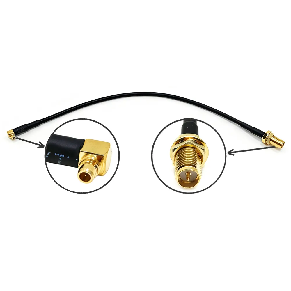
Sourcing a reliable RF coaxial cable assembly for a new engineering project can feel like navigating a maze. With so many variables—impedance, frequency capability, insertion loss, shielding, jacket material, and connector styles—picking the right component is rarely simple. Every design parameter impacts signal integrity, and none of them works in a vacuum.
Whether setting up cellular infrastructure, industrial automation, or lab‑grade test equipment, getting the specification right from day one saves time and protects the project budget.
Core Specifications That Dictate Performance
Before comparing physical cable builds, it helps to break down what the numbers on a spec sheet actually mean in real‑world applications.
| Specification | Primary Impact | Key Consideration |
|---|---|---|
| Impedance | Signal reflection & matching | 50Ω for RF/data; 75Ω for TV/video |
| Insertion Loss | Signal strength attenuation | Increases with length & frequency |
| VSWR & Return Loss | Transmission efficiency | Target 1.3:1 or better |
| Shielding | Ingress & egress noise control | Essential in high‑EMI environments |
System Impedance
Most high‑frequency systems operate on a 50Ω standard, particularly in telecommunications, radar, and wireless networking. Broadcast television and video networks typically run on 75Ω. Mismatching system impedance along the signal line causes energy reflections, standing waves, and noticeable signal distortion. Matching this baseline requirement is always step one.
Insertion Loss
Insertion loss measures how much signal power dies out as energy moves down the line. Loss scales directly with cable length and operating frequency. Conductor resistance grows with the square root of frequency, while dielectric loss increases linearly.
When specifying a high frequency coaxial cable running above 6 GHz, dielectrics like expanded PTFE offer significantly lower loss than standard polyethylene. While low‑loss materials cost slightly more upfront, they preserve link budgets across critical signal paths.
VSWR and Return Loss
Voltage Standing Wave Ratio (VSWR) tracks how much energy bounces back toward the transmitter due to impedance discontinuities. Lower numbers mean better matching; a quality RF coaxial cable assembly typically aims for a VSWR between 1.3:1 and 1.4:1 across its rated band.
Connector crimp quality and assembly uniformity drive VSWR performance. A minor flaw in connector termination or a tight kink in the cable can ruin an otherwise excellent VSWR rating.
Shielding Effectiveness
Shielding keeps unwanted external interference out while keeping your signal from radiating into nearby circuits. In noisy industrial environments, medical rooms, or crowded equipment racks, high shielding effectiveness (often 85 dB or better) matters just as much as low attenuation.
Choosing the Right Construction Type
Coaxial cables fall into three primary physical categories. Balancing flexibility, attenuation, and physical durability determines which style best fits the mechanical setup.
Flexible Cables
Flexible designs utilize braided outer conductors and flexible dielectrics. They shine in setups requiring frequent routing around corners, service loops, or repeated repositioning.
Looking at standard rg6 coaxial cable specifications, these cables provide versatile options for short‑to‑medium runs, balanced shielding, and predictable flexibility. However, repeated bending eventually causes micro‑deformations in the shield and dielectric. Over time, this mechanical wear causes insertion loss to rise and VSWR to degrade. For long‑term installations, keeping the bend radius 1.5 to 2 times wider than the absolute minimum rating extends operating life significantly.
Semi‑Rigid and Conformable Assemblies
Semi‑rigid cables replace outer wire braids with a solid copper or aluminum tube shield. This construction provides near‑perfect 100% RF shielding, excellent phase stability across temperature shifts, and minimal attenuation.
Heavy‑duty options like the rg 393 coaxial cable or SS402 style semi‑rigid lines serve as the backbone for high‑density instrument racks, phased array antennas, and aerospace electronics. The trade‑off is mechanical flexibility: semi‑rigid assemblies must be precision‑bent to their final shape using specialized tools before final installation.
Hardline Feeder Lines
Hardline assemblies feature thick corrugated metallic outer shields and air or foam dielectrics. Used primarily for long antenna feeder lines on cellular towers and broadcast infrastructure, hardline cable minimizes path loss over long distances. They rely on heavy‑duty mechanical clamping connectors rather than crimped or soldered joints.
Matching Cable Specs to Industry Requirements
Every industry puts different pressures on a cable assembly. Sourcing decisions must align with these specific operational demands:
- Telecom Infrastructure: Focuses on low attenuation over extended cable runs, tight weatherproofing, UV resistance, and wide operating temperature ranges.
- Industrial Automation & Transportation: Demands high shielding effectiveness to combat severe EMI, high vibration‑resistant coupling mechanisms, and oil‑resistant or flame‑retardant outer jackets.
- Medical & Laboratory Testing: Prioritizes phase stability, precise calibration data, non‑magnetic materials, and documented traceability.
- Aerospace & Defense: Requires adherence to military specs (such as MIL‑DTL‑17 and MIL‑STD‑348), extreme temperature tolerance, and full traceability across the supply chain.
Procurement Checklist Before Placing an Order
Before releasing a purchase order for a production run of RF cable assemblies, running through this simple sanity check avoids costly retrofits down the road:
- System Impedance: Are all connectors, cables, and board interfaces strictly matched to 50Ω or 75Ω?
- Frequency Headroom: Does the cable cutoff frequency comfortably exceed the system's maximum operating frequency?
- Loss Budget: Have you calculated total path attenuation at peak operating frequency, including connector loss?
- Mechanical Clearance: Is the physical routing planned to respect the cable's recommended dynamic and static bend radii?
- Environmental Ratings: Will the outer jacket handle temperature extremes, UV exposure, chemicals, or moisture?
- Connector Integrity: Are the connector interfaces (SMA, N‑Type, BNC, TNC, or micro‑connectors) rated for the required mating cycles and environmental seal levels?
Partnering for Custom Cable Integration
Standard off‑the‑shelf assemblies cover routine bench testing, but custom engineering projects often demand tailored solutions—such as exact pinouts, mixed connector types, specialized jacket material for tight enclosures, or pre‑tested phase‑matched pairs.
When off‑the‑shelf options fall short, working with a specialized manufacturer like CNRFConnectors streamlines custom design and volume procurement. Reliable supply partners provide tailored RF coaxial cable assembly configurations, precision semi‑rigid bending, comprehensive swept frequency test reports, and quick‑turn prototyping to ensure seamless system integration from day one.





