 EN
EN

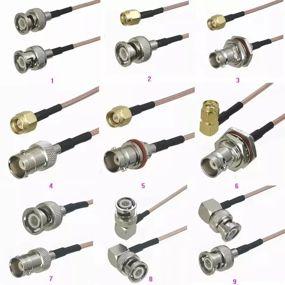
Selecting an rf coaxial cable involves much more than picking a convenient outer diameter and hoping the datasheet matches real-world performance. For an RF systems engineer or procurement buyer, the center conductor, dielectric insulator, outer shielding braid, and protective jacket operate as an integrated transmission system. Together, these layers determine signal attenuation, characteristic impedance, shielding effectiveness, mechanical flexibility, and long-term installation cost.
This is why two cables that look virtually identical in a product catalog can perform completely differently inside a radio transmitter, antenna tower, test fixture, or broadcast video link. Balancing electrical requirements with physical routing constraints ensures long-term signal reliability.
Analyzing Coaxial Cable Construction from the Inside Out
The Center Conductor: Balancing Attenuation and Flex Life
The center conductor carries high-frequency signal current along the transmission line. Solid copper conductors deliver low electrical resistance and stable internal geometry, making them ideal for fixed infrastructure runs. Conversely, a stranded center conductor provides superior flex life, which is essential for robotic applications, portable test leads, and patch cables that experience repeated bending.
At high radio frequencies, signal current concentrates near the outer surface of the conductor due to skin effect. While larger conductor diameters reduce attenuation, conductor size also dictates characteristic impedance. Engineers must evaluate attenuation curves at target operating frequencies and planned run lengths rather than choosing conductors based on diameter alone.
The Dielectric Layer: Maintaining Impedance Alignment
The dielectric insulator maintains precise physical spacing between the inner conductor and outer shield, preserving line impedance. Solid polyethylene serves standard general-purpose lines well, while foamed polyethylene introduces microscopic air bubbles to reduce dielectric loss and lower signal attenuation. PTFE insulators handle high temperatures and provide extreme electrical stability in demanding military or aerospace environments.
System impedance must remain consistent across the entire signal path. A 75 ohm coaxial cable belongs in television, CATV, and video distribution networks where equipment ports are designed for 75 Ohms. Connecting 75-ohm hardware to a 50-ohm wireless path creates impedance discontinuities, driving up return loss and causing unwanted signal reflections.
The Outer Shield: Signal Containment and EMI Protection
The outer conductor serves as both the electrical return path and the electromagnetic shield preventing RF leakage. Single-braid shielding offers good flexibility for internal routing, whereas foil-plus-braid constructions provide broader frequency coverage against external electromagnetic interference (EMI). Multiple braid layers enhance physical durability, while corrugated copper outer shields deliver maximum signal containment across long outdoor feeder runs.
Shielding requirements depend on the surrounding environment. Routing cable through a shielded enclosure requires different protection levels than running lines past high-power switching power supplies or heavy industrial machinery.
The Protective Outer Jacket: Environmental Resistance
While the outer jacket does not affect electrical impedance directly, it determines whether a cable assembly survives environmental exposure. Standard PVC suits indoor cabinet wiring, whereas polyethylene jackets resist moisture and UV degradation in outdoor deployments. Flame-retardant or fluoropolymer jackets fulfill strict building codes for plenum spaces and high-temperature industrial environments.
Comparing Coaxial Form Factors for Targeted Applications
Different installation routes require specific cable geometries:
-
Flexible Coaxial Lines: Designed for equipment interconnects, patch bays, and general wiring harnesses where easy routing and field serviceability are required.
-
Semi-Rigid Coaxial Lines: Utilized inside microwave instruments and compact radio modules where precise shape retention and maximum shielding effectiveness are critical.
-
Hardline and Corrugated Feeders: Built for high-power broadcast towers and cellular base stations requiring ultra-low loss over long vertical runs.
Even widely used industry standards like rg213 coaxial cable require detailed specification review. Different manufacturing variants of rg213 coaxial cable feature distinct braid coverage percentages, dielectric materials, and jacket ratings that affect power handling and cable lifespan.
Selecting Matching Connector Interfaces
Choosing compatible rf coaxial cable connectors is just as critical as selecting the bulk cable itself. A connector head must match the exact outer jacket diameter, shield braid construction, dielectric dimensions, and center conductor gauge of the targeted cable.
Achieving a low-loss junction requires dedicated crimp dies, clamp hardware, stripping tools, and precise assembly instructions. Using mismatched connectors distorts dielectric geometry at the interface, creating localized impedance spikes and elevated return loss.
For high-volume production builds, specifying factory-terminated assemblies with documented VSWR and insertion loss test reports prevents assembly errors and accelerates field installation schedules.
Essential Procurement Framework for OEM Buyers
When compiling engineering specifications for custom assemblies or bulk cable spools, document the following requirements:
-
Operating Frequency and Attenuation Limits: Define the operational band, maximum cable run length, and allowable insertion loss budget.
-
System Impedance Alignment: Verify 50-Ohm or 75-Ohm impedance matching across transmitters, cables, adapters, and antennas.
-
Environmental Operating Conditions: Specify UV exposure levels, temperature limits, flame ratings, and chemical or moisture resistance needs.
-
Mechanical Routing Constraints: Identify outer diameter limits, minimum bend radii, continuous flex cycle requirements, and pull-strength tolerances.
Streamlining RF Infrastructure with Precision Manufacturing
Deploying reliable wireless systems requires sourcing coaxial hardware from manufacturing partners who maintain tight dimensional tolerances, high-grade plating, and dependable supply chains. Inconsistent dielectric dimensions or poor braid coverage lead to impedance shifts, elevated path loss, and unexpected field downtime.
Worldpeak delivers precision-engineered rf coaxial cable assemblies, specialized rf coaxial cable connectors, adapters, and bulk transmission lines for telecom, industrial automation, and broadcast applications worldwide. Supported by automated production infrastructure and comprehensive quality testing, Worldpeak provides robust 50-Ohm and 75-Ohm interconnect solutions tailored to demanding global deployments.
Whether your next project calls for flexible 75 ohm coaxial cable spools, heavy-duty rg213 coaxial cable jumper runs, or custom panel-mount pass-throughs, Worldpeak offers factory-direct supply programs designed to keep network infrastructure deployments running smoothly.
Frequently Asked Questions
What is the main difference between 50-Ohm and 75-Ohm coaxial cables?
A 50-Ohm cable configuration optimizes power handling capacity, making it the industry standard for wireless transmitters, cellular equipment, and Wi-Fi networks. A 75 ohm coaxial cable optimizes signal voltage attenuation, making it ideal for carrying video signals, CATV, and digital TV broadcasts over long distances.
How does bend radius impact coaxial cable performance?
Bending a coaxial line tighter than its specified minimum bend radius compresses the internal dielectric insulator, forcing the center conductor off-center. This mechanical deformation alters local impedance, causing signal reflection and elevated return loss.
Can standard coaxial connectors fit any cable with similar dimensions?
No. Specialized rf coaxial cable connectors must match the exact conductor gauge, dielectric profile, and shield construction of the specific cable model. Using generic hardware leads to bad mechanical crimps, intermittent pin contact, and poor weather sealing.





