 EN
EN

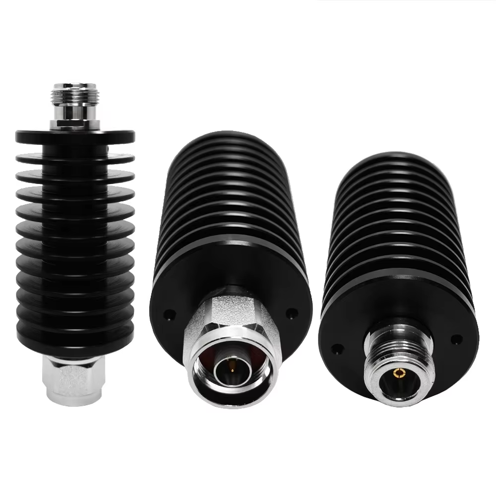
Building a high-performance wireless system involves much more than connecting part numbers on an engineering schematic. For a system integration engineer, choosing the right rf components dictates signal margin, noise thresholds, thermal endurance, and field serviceability. Every coupler, filter, attenuator, and cable run plays a active role in total system behavior across 5G infrastructure, defense hardware, and lab test benches.
Analyzing the entire signal chain rather than isolated data sheets keeps projects on budget and prevents unexpected performance drops during field deployment.
Starting with the Signal Path Map
Before ordering hardware, mapping out the signal path from transmitter output to the terminal antenna or receiver input establishes baseline requirements. Identifying every split, test access point, frequency conversion, and cable transition reveals the true operating constraints of the system.
Cumulative insertion loss demands immediate attention. While a loss of 0.2 dB through a single inline connector seems negligible, combining multiple adapters, long feeder cables, and attenuators quickly consumes signal headroom. Likewise, selecting hardware rated for average transmit power without accounting for high peak-to-average power ratios (PAPR) leads to premature component burn-out.
Evaluating electrical parameters as an interconnected budget ensures every hardware block supports total signal integrity.
Core Building Blocks in Modern RF Chains
Directional Couplers for Non-Intrusive Monitoring
Directional couplers extract a precise fraction of signal power from the main transmission line without disrupting primary signal flow. This allows engineering teams to monitor forward transmit power, track reflected power from mismatched antennas, or feed local measurement loops. Essential selection metrics include coupling factor, directivity, mainline insertion loss, and power capacity across the operational band.
Attenuators for Level Control and Receiver Protection
Fixed and variable attenuators adjust signal power to predictable levels, shielding sensitive receiver front-ends from overdriven signals. When selecting inline attenuators, verifying attenuation flat tolerance across the entire band, heat dissipation capacity, and return loss performance prevents unwanted reflection back toward signal generators.
Filters for Bandpass Precision and Interference Rejection
Bandpass, lowpass, and highpass filters define spectral boundaries by suppressing harmonic spurious emissions and blocking out-of-band noise. The primary design trade-off centers on passband insertion loss versus out-of-band attenuation steepness. In dense wireless networks, well-designed filters prevent co-located radios from desensitizing adjacent receiver channels.
Frequency Doublers and Signal Conversion
A frequency doubler generates output energy at twice the fundamental input frequency, providing a practical method for reaching higher microwave bands without redesigning the primary signal source. When selecting a doubler, engineers evaluate conversion loss, harmonic suppression, required input drive level, and the need for downstream filtering to isolate desired output signals.
Three Technical Metrics That Dictate System Fit
-
Frequency Band Coverage: Confirm that hardware specifications cover the primary operating band alongside necessary safety margins and harmonic frequencies.
-
Insertion Loss Budget: Calculate cumulative attenuation across all inline devices to protect system signal-to-noise ratio (SNR).
-
Power and Thermal Limits: Ensure continuous average and peak power ratings account for real-world ambient temperatures and mismatch reflections.
Maintaining impedance consistency across every junction remains equally vital. An unexpected jump from a 50-Ohm trace to an unverified adapter introduces reflections that degrade total system return loss.
Adapting Component Selection to Deployment Environments
Industrial and Cellular Infrastructure
Cellular base stations and outdoor wireless setups prioritize low signal loss, compact routing, and long-term weatherproofing. Reducing unnecessary cable adapters lowers failure points across outdoor feeder runs. Using high-flex corrugated copper feeder lines maintains reliable 50-Ohm connections across tight tower enclosures.
Defense and Aerospace Hardware
Military platforms emphasize mechanical durability, vibration resistance, extreme temperature stability, and electromagnetic shielding. Hardware selected for defense applications must withstand severe physical shock without compromising internal pin alignment or outer shell sealing.
Test Bench and Measurement Laboratories
Laboratory setups demand strict repeatability. Utilizing calibrated attenuators, stable test leads, and low-PIM couplers prevents measurement drift. Establishing clean inspection habits for every rf connection ensures consistent baseline calibration over thousands of testing cycles.
Practical Checklist for Engineering Procurement
Follow this structured workflow to streamline component selection and hardware verification:
-
Map the Signal Path: Document every transition point, operating frequency, signal level, and impedance boundary from source to load.
-
Establish Electrical Limits: Define maximum acceptable path loss, required harmonic rejection, and peak power headroom.
-
Select Functional Modules: Pair functional requirements with targeted hardware—couplers for sampling, attenuators for level tuning, and filters for band isolation.
-
Inspect Physical Interfaces: Verify outer shell gender, center pin styles, mounting dimensions, and cable strain relief specs.
-
Perform Full System Validation: Test the complete assembled signal path across all operational frequencies rather than relying purely on standalone component data sheets.
Frequently Asked Questions
How should hardware selection be reviewed before purchase?
Review all hardware against a complete signal chain diagram at maximum and minimum operating frequencies rather than relying on single mid-band center points. Requisition packages should clearly state required frequency bands, power limits, insertion loss limits, housing dimensions, and acceptance testing criteria to align procurement with engineering targets.
What factors make an RF junction reliable over time?
A dependable physical connection relies on matched interface series, clean contact surfaces, and proper installation torque. Inspecting center pins for contamination, maintaining proper cable bend radii, and eliminating extra inline adapters reduces signal reflection and extends hardware lifespan.
When are microwave components preferred over general-purpose hardware?
Higher frequency bands demand tight physical tolerances and specialized dielectric materials. Purpose-built microwave components deliver predictable performance across higher frequency ranges where standard connectors introduce excessive signal attenuation and return loss degradation.
How should a frequency converter block be specified?
Specifying a frequency conversion stage requires defining input frequency range, target output band, required drive power, allowable spurious product limits, and heat dissipation requirements. Evaluating the rf converter alongside its supporting filters and amplifiers ensures clean frequency conversion across varying operational temperatures.
Streamlining RF Systems with Dependable Manufacturing
Integrating complex wireless hardware requires working with manufacturing partners who deliver tight mechanical tolerances, robust surface plating, and reliable global supply chain support. Inconsistent connector dimensions or low-grade dielectric materials introduce signal reflection and increase troubleshooting downtime.
Worldpeak delivers precision-engineered RF interconnects, coaxial adapters, custom cable assemblies, and specialized hardware modules for industrial, telecom, and broadcast applications worldwide. Backed by modern manufacturing lines and strict quality assurance protocols, Worldpeak provides custom interface solutions and dependable factory-direct supply programs tailored to complex system integration requirements.
Whether your next build calls for high-power coaxial interconnects, specialized panel pass-throughs, or custom cable assemblies, partnering with Worldpeak keeps network infrastructure deployments reliable and on schedule.





