 EN
EN

What environmental resistance can be customized for OEM rf cable
2026/09/25
Customize an rf high frequency cable for temperature, moisture, corrosion, vibration, flexing, and OEM validation needs.
2026/09/08
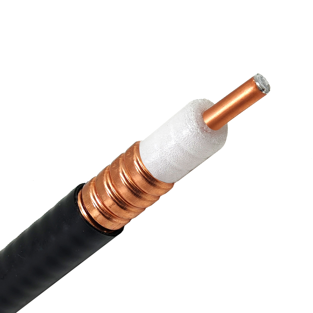
Connecting ground-level transmitter equipment to top-mounted antennas represents one of the largest potential sources of power loss across any wireless network. For antenna towers ranging between 50 and 300 feet in height, cumulative attenuation inside an RF feeder cable can easily exceed 10 dB. In practical terms, losing 10 dB means over 90 percent of the transmitter's output power turns into dissipated heat before reaching the radiating elements.
Calculating an accurate antenna tower loss budget is essential for telecom planners, broadcast engineers, and network operators. Balancing overall feeder cable attenuation against physical cable weight, wind load, and installation budget ensures long-term link reliability across commercial cellular, public safety, and private wireless installations.
Signal degradation within an RF feeder cable stems from two distinct physical sources: conductor loss and dielectric loss.
At microwave frequencies above 1 GHz, dielectric absorption dominates total feeder cable attenuation. Standard flexible coaxial cables like RG-213 or LMR-400 suit shorter jumper runs under 100 feet at lower frequencies. However, tall antenna tower loss budget requirements demand air-dielectric or low-loss foam coaxial lines.
Corrugated copper coax line, commonly known as heliax cable, delivers lower loss per foot than flexible braider alternatives. For example, a 7/8-inch heliax cable exhibits roughly 1.5 dB of feeder cable attenuation per 100ft at 900 MHz, whereas standard LMR-400 exhibits roughly 3.9 dB under identical conditions.
Selecting the proper RF feeder cable involves balancing physical cable size, bend radius limits, and attenuation metrics across operating bands.
| Cable Type | Feeder Cable Attenuation (dB/100ft @ 2.4 GHz) | Total Loss over 150ft + Connectors | Power Reaching Antenna (30 dBm Input) |
|---|---|---|---|
| RG-213 Coax | 8.5 dB | 13.8 dB | 16.2 dBm (42 mW) |
| LMR-400 UF | 6.6 dB | 10.9 dB | 19.1 dBm (81 mW) |
| 1/2" Heliax Cable | 3.2 dB | 5.8 dB | 24.2 dBm (263 mW) |
| 7/8" Heliax Cable | 1.8 dB | 3.7 dB | 26.3 dBm (427 mW) |
Reviewing these attenuation numbers highlights why choosing low-loss heliax cable structures matters for longer vertical tower runs. Switching from flexible coax to 7/8-inch corrugated cable boosts radiated antenna power significantly over a 150-foot vertical span.
Evaluating a 150-foot antenna tower installation for a 2.4 GHz Wi-Fi backhaul link illustrates how cable selection impacts overall system link margins.
Assuming a transmitter output power of 30 dBm (1 Watt):
Upgrading the main RF feeder cable more than triples the effective power delivered to the antenna radiating elements, turning a marginal wireless connection into a robust link.
When an antenna tower loss budget shows excessive line loss, installing a tower top amplifier (TTA) provides an alternative way to preserve link margins. Mounted directly at the top of the tower near the antenna, a tower top amplifier boosts incoming weak signals before they suffer feeder cable attenuation on the long descent down to base station receivers.
While a tower top amplifier improves uplink receiver sensitivity, it introduces additional hardware expense, requires tower-mounted DC bias injection, and creates a potential point of failure exposed to lightning strikes and weather extremes. Selecting a lower loss RF feeder cable during initial construction remains the most reliable primary strategy for optimizing overall link performance.
Even the highest grade heliax cable loses performance if paired with poorly installed connectors. A loose flare joint or dirty mating surface on a corrugated RF feeder cable can add 0.5 to 1.0 dB of extra insertion loss while creating high VSWR reflections back into high-power amplifiers.
Deploying long-distance wireless links requires reliable interconnect hardware built to handle harsh environmental conditions. Modern telecom networks depend on precision-engineered RF feeder cable jumpers, weather-sealed terminations, and low-loss connector adapters to maintain system link margins.
Specialized coaxial equipment suppliers like WORLDPEAK support global infrastructure buildouts with custom RF feeder cable assemblies and precision connector options. Maintaining complete CNC machining, automated plating, and full vector network analyzer testing infrastructure, WORLDPEAK delivers custom heliax cable terminations and low-PIM jumper assemblies tailored to exact field specifications. Adhering to strict international ISO quality management systems, WORLDPEAK supplies durable, factory-tested coaxial solutions to telecommunications, broadcast, and defense sector clients worldwide.

2026/09/25
Customize an rf high frequency cable for temperature, moisture, corrosion, vibration, flexing, and OEM validation needs.

2026/09/25
Streamline RF equipment assembly lines with custom coaxial jumpers. Reduce line-side rework, ensure precise routing, and boost production efficiency.

2026/09/25
Learn PL-259 connector selection, soldering, weatherproofing, and RF applications for dependable antenna feedlines.

2026/09/25
Confirm impedance for a 90 degree coax connector with an ODM test plan covering VNA setup, VSWR, acceptance criteria, and release records.

2026/09/25
Learn when an n type coax connector can omit extra anti-corrosion treatment and when OEM exposure conditions require it.

2026/09/25
Learn how the custom cable and wire sample process helps ODM buyers validate design, testing, and production readiness.