 EN
EN

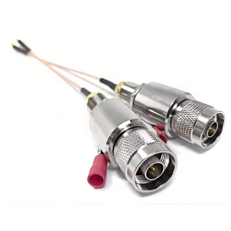
Outdoor antennas give wireless communications and telemetry networks exceptional reach, but elevated metal structures also invite transient surge energy. Direct lightning strikes, nearby cloud-to-ground discharges, and electrostatic switching events induce high voltage spikes onto transmission lines. Without inline surge suppression, these transients travel along feeder cables directly into sensitive receiver front-ends, low-noise amplifiers, and network switches, resulting in destroyed electronics and costly site downtime.
Installing a dedicated rf lightning arrestor at the facility perimeter establishes a low-impedance diversion path. By shunting destructive current straight to the master grounding bus before it enters the equipment room, inline surge protectors keep wireless infrastructure operational through severe weather events.
How Surge Energy Infiltrates Coaxial Lines
While a direct strike to an antenna mast represents an extreme event, indirect magnetic coupling from nearby strikes causes the vast majority of equipment failures. A lightning discharge occurring hundreds of meters away induces thousands of volts onto surrounding copper cabling.
When a strike occurs, electromagnetic fields create sudden potential differences between the antenna structure, cable shield, equipment rack, and building earth ground. The coaxial feeder becomes the primary path for ground potential equalization. High transient voltages breach the dielectric barrier inside coaxial connectors, jumping to the center conductor and frying active silicon components inside connected radios.
Mounting an rf lightning arrestor directly at the bulkhead boundary ensures that voltage spikes encounter a controlled breakdown path immediately upon entering the building enclosure.
Gas Discharge Tubes and Hybrid Protection Technologies
Selecting the right inline protector requires matching the internal breakdown mechanism to the electrical demands of the signal line. Different transient protection architectures serve distinct roles across high-frequency transmission systems:
Gas Discharge Tube Technology
Gas Discharge Tubes (GDT) remain the most widely used protection mechanism for high-frequency coaxial lines. Under normal operational conditions, the gas capsule maintains extremely high impedance and low capacitance, allowing RF signals to pass with virtually no insertion loss or VSWR degradation.
When a high transient voltage crosses the spark gap, the gas ionizes within nanoseconds, creating a low-resistance short circuit that routes high surge currents safely to ground. Once the surge passes, the gas de-ionizes and returns to its high-impedance state. GDT devices come in both DC-blocked and DC-pass configurations, allowing DC voltage to power remote masthead electronics like Low Noise Blockers (LNBs) or Tower Mounted Amplifiers (TMAs).
Metal Oxide Varistor Clamping
Metal Oxide Varistors (MOVs) alter internal resistance as voltage increases. While widely deployed in low-frequency power panels and control circuits, their inherent junction capacitance can alter return loss and attenuate high-frequency microwave signals. MOVs are generally reserved for low-speed data lines or power feeding cables rather than main microwave RF links.
Multi-Stage Hybrid Protectors
Hybrid suppressors combine fast-acting silicon avalanche diodes with heavy-duty gas tubes. The diode clamps rapid voltage transients in picoseconds, while the primary GDT diverts the bulk of the high-amperage current. Hybrid designs excel in ultra-sensitive receiver paths that demand low let-through voltage.
| Protection Type | Response Speed | Capacitance Load | Ideal Application |
|---|---|---|---|
| Gas Discharge Tube (GDT) | Nanoseconds | Extremely Low | High-Frequency Coaxial Lines |
| Metal Oxide Varistor (MOV) | Nanoseconds | Medium to High | AC/DC Power & Control Lines |
| Hybrid (GDT + Diode) | Picoseconds | Low to Medium | Precision Receiver Systems |
Grounding Rules and Perimeter Boundary Installation
A surge protector is only as effective as the grounding system backing it up. Even a top-tier suppressor cannot protect equipment if wired to a long, high-inductance ground lead.
-
Establish a Strict Entry Zone: Mount all coaxial arrestors on a single, heavy-gauge copper entry plate or bulkhead panel where feeders enter the building shelter.
-
Keep Earth Leads Short and Straight: High-frequency surge currents view sharp bends and long wires as massive electrical impedance. Run ground straps as straight as possible directly to the ring ground.
-
Maintain Equipotential Bonding: Connect the RF bulkhead plate, equipment racks, AC surge protectors, and tower base grounding to a single master ground bus to prevent dangerous differential voltages.
Distinguishing RF Protectors from External Rods and DC Arrestors
System designers must differentiate between inline RF coaxial protection, external air terminals, and direct current surge suppression. Confusing these distinct categories leads to improper field installations and unprotected hardware.
External Air Terminals vs. Coaxial Line Protection
An early streamer emission terminal, commonly referenced as an ese lightning arrester, sits atop tall masts to attract lightning strikes and direct the stroke to earth via dedicated downconductors.
Procurement teams analyzing an ese lightning arrester price must recognize that structural air terminals and inline coaxial suppressors are complementary, not interchangeable. The overall ese lightning arrester price reflects specialized stainless steel air terminals designed for structural protection, whereas an inline rf lightning arrestor is a specialized RF component engineered for signal line integrity.
Solar DC Protectors vs. Coaxial Surge Suppressors
Similarly, a lightning arrester for solar panels is engineered specifically for high-voltage DC power arrays.
System Selection Checklist for Integration
Before choosing an inline suppressor, engineering teams should evaluate these core operational parameters:
-
Frequency Range and Impedance: Match the operating band (e.g., DC to 6 GHz) and maintain strict 50-ohm or 75-ohm line impedance.
-
DC Pass or DC Block Configuration: Confirm whether the line carries DC bias voltage to power remote masthead electronics.
-
Connector Compatibility: Select native interfaces (Type N, SMA, 4.3-10, 7/16 DIN) to eliminate unnecessary adapter transitions.
-
Power Handling Capacity: Verify that continuous wave (CW) and peak power ratings exceed maximum transmitter output.
-
Surge Current Rating: Ensure the unit handles standard surge waveforms (e.g., 8/20 µs or 10/350 µs) up to 10 kA or 20 kA levels.
End-to-End Line Reliability with Worldpeak
Protecting high-frequency wireless infrastructure requires absolute reliability across every cable junction, connector interface, and protective device. Installing high-grade surge protection on a transmission line with poorly fitted connectors or degraded jumpers still leaves systems vulnerable to standing waves, moisture ingress, and thermal failure.
Worldpeak supports global telecommunications, broadcast, and industrial telemetry networks with premium RF connectors, low-loss coaxial cable assemblies, precision adapters, and passive signal accessories. By applying stringent CNC machining tolerances, advanced weather-sealing designs, and comprehensive sweep testing for insertion loss and return loss, Worldpeak delivers the high-integrity interconnect hardware needed to maintain seamless communications through demanding outdoor environments.





