 EN
EN

7/16 DIN Connector Guide: High-Power RF Standard
2026/09/24
Choose a 7 16 connector for high-power RF: compare DIN and Type N, protect PIM margin, and apply field installation checks.
2026/09/08
Integrating microwave components into high-density wireless devices requires balancing mechanical flexibility with low signal attenuation. The SubMiniature version A interface remains the absolute standard for microwave signals from DC up to 18 GHz and beyond. When setting up an RF to SMA transition, system designers face a fundamental choice: use a flexible cable assembly or install a rigid inline adapter.
Selecting between an assembly like an SMA pigtail and a direct adapter alters your link budget, physical space requirements, thermal stress tolerances, and vibration survival rates. Understanding how different SMA connector types perform across tight enclosures helps hardware teams pick the right RF connector SMA configuration for IoT devices, cellular infrastructure, and laboratory test benches.
An SMA pigtail consists of a short length of flexible micro-coaxial cable—typically between 2 and 12 inches—terminated with an SMA interface on one end and a secondary micro-connector on the opposite side. Common board-side options include U.FL, IPEX, MCX, MMCX, or direct solder leads.
In-line adapters provide a direct, rigid transition between two interfaces without using an intermediate cable section. An inline RF connector SMA adapter might transition from N-type to SMA, BNC to SMA, or TNC to SMA. These components are ideal when two mating ports rest close together inside a shielded enclosure.
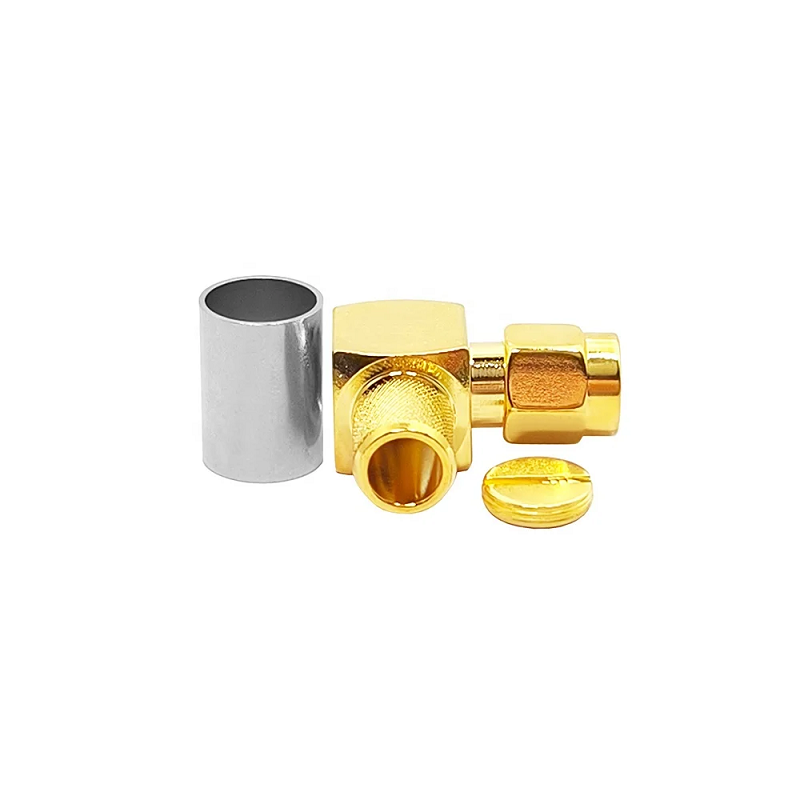
When enclosure depth is constrained, a standard straight adapter puts excessive lateral bending strain on connected coaxial cables. In these scenarios, a right angle SMA adapter changes the signal path direction by 90 degrees. Maintaining exact 50-ohm characteristic impedance through a 90-degree corner requires precise internal machining of center contact pins and dielectric insulation layers. Using a high-precision right angle SMA adapter prevents cable kinking, preserves return loss performance, and keeps cable routing parallel to instrument front panels or enclosure walls.
Evaluating core parameters across common SMA connector types helps clarify trade-offs between physical assembly flexibility, power loss, and mechanical stability.
| Selection Metric | Flexible SMA Pigtail | In-Line RF to SMA Adapter | Right Angle SMA Adapter |
|---|---|---|---|
| Typical Insertion Loss | 0.3 dB – 0.8 dB | 0.1 dB – 0.25 dB | 0.15 dB – 0.35 dB |
| Mechanical Alignment | High Flexibility / Dynamic Bend | Rigid Straight Path | Fixed 90-Degree Turn |
| Vibration Isolation | Excellent (Cable Absorbs Shock) | Poor (Transfers Load) | Poor (Transfers Load) |
| Enclosure Footprint | Requires Routing Clearance | Short Linear Footprint | Low Profile / Tight Corner |
| Primary Bandwidth | DC – 6 GHz (Cable Dependent) | DC – 18 GHz+ | DC – 18 GHz+ |
| Common Application | PCB Module to Panel Bulkhead | Chassis to Chassis Joint | Dense Racks / Panel Corners |
Examining real-world hardware integration examples shows how matching specific SMA connector types to exact physical demands optimizes overall RF to SMA link reliability:
Following consistent installation practices ensures low return loss and long-term joint stability across any RF connector SMA project:
Delivering clean microwave performance across complex RF to SMA configurations requires tight mechanical machining tolerances and high-grade plating finishes. Minute air gaps or unpolished interior corners inside a right angle SMA adapter can create phase distortion and unwanted reflections at high frequencies.
Specialized coaxial equipment manufacturers like WORLDPEAK support global telecommunications, defense, and laboratory testing clients with a complete range of SMA connector types and customized interconnect solutions. Utilizing multi-axis CNC machining, high-grade gold plating, and 100 percent vector network analyzer testing infrastructure, WORLDPEAK delivers custom SMA pigtail harnesses, high-frequency in-line adapters, and low-loss right angle SMA adapter units tailored to exact client requirements. Adhering strictly to international ISO quality systems, WORLDPEAK provides dependable, factory-certified coaxial hardware to system integrators worldwide.

2026/09/24
Choose a 7 16 connector for high-power RF: compare DIN and Type N, protect PIM margin, and apply field installation checks.

2026/09/24
Compare TNC connector types, specs and applications, including RP-TNC, bulkhead options, vibration performance and adapter selection.

2026/09/24
Understand MMCX connector basics, RF limits, and how to choose the right coaxial interface for compact systems.

2026/09/24
Understand RP-SMA connector polarity, mating rules, frequency checks, and OEM termination options for reliable RF builds.

2026/09/24
Choose the right bnc male connector for RF, CCTV and test systems with clear 50Ω vs 75Ω, type and installation guidance.

2026/09/24
Compare LMR400 specs, cable loss, uses, connectors and RG8/RG213 alternatives with a practical RF loss-budget method.