 EN
EN

What environmental resistance can be customized for OEM rf cable
2026/09/25
Customize an rf high frequency cable for temperature, moisture, corrosion, vibration, flexing, and OEM validation needs.
2026/09/08
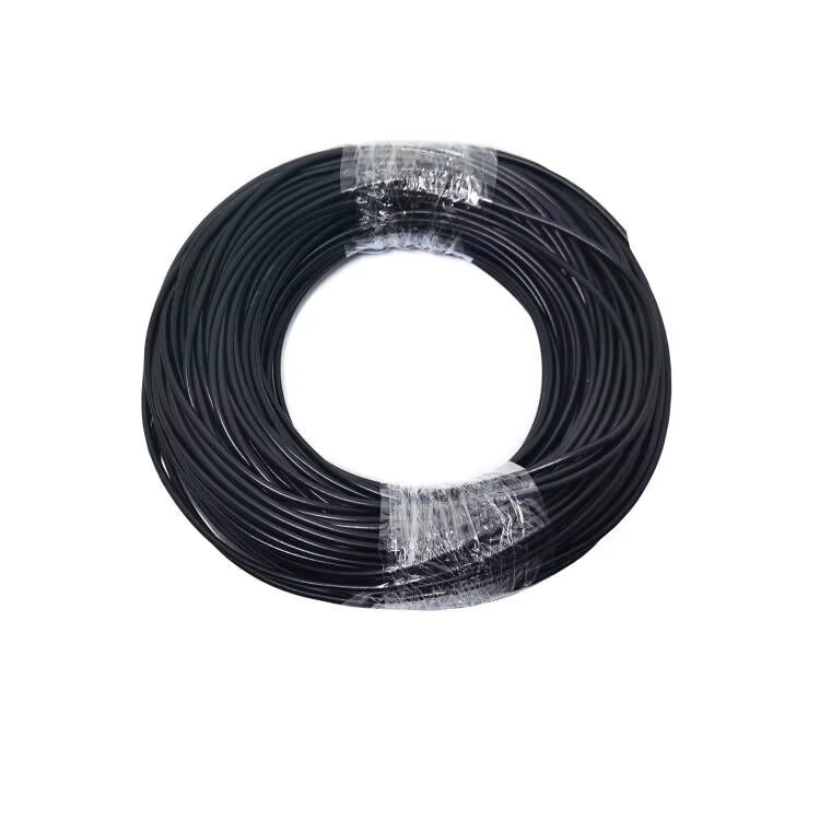
Designing compact wireless devices requires careful choices when routing high-frequency signals through tight spaces. As electronic enclosures shrink, traditional thick coax lines become impossible to bend around internal battery packs, display ribbon cables, and circuit boards. An RG174 coaxial cable provides an ideal combination of low profile, extreme flexibility, and stable 50-ohm impedance, making it a go-to solution for short-distance internal RF wiring.
Understanding the mechanical limits, electrical attenuation curves, and termination best practices for an RG174 coaxial cable allows hardware design teams to preserve signal integrity while keeping device form factors slim. From wearable IoT trackers to commercial Wi-Fi access points, using a high-quality PCB coaxial cable assembly avoids unexpected link budget drops.
Evaluating any RG174 application begins with examining its physical layers. An RG174 coaxial cable features an outer jacket diameter of approximately 0.110 inches (2.8 mm), allowing it to bend around tight radii where larger cables would kink or crack.
Because an RG174 coaxial cable has a thin dielectric, attenuation levels rise faster across frequency compared to thicker coaxial lines. At 100 MHz, loss sits at roughly 5.5 dB per 100ft. At 400 MHz, attenuation increases to 13.5 dB per 100ft, reaching nearly 22 dB per 100ft at 1 GHz. While these loss numbers seem high over long cable runs, typical micro coax pigtail applications use short lengths between 2 and 12 inches. Over a 6-inch jumper, the total insertion loss remains under 0.2 dB at 900 MHz, making it an efficient choice for internal board-to-chassis links.
Selecting the correct transmission line requires matching cable dimensions and electrical properties to system needs. Comparing a 50-ohm RG174 coaxial cable with a 75-ohm RG 59 U coaxial cable highlights why impedance matching is essential during PCB coaxial cable selection.
| Cable Parameter | RG174 Coaxial Cable | RG 59 U Coaxial Cable |
|---|---|---|
| Impedance | 50 Ohms | 75 Ohms |
| Outer Diameter | 0.110 inches (2.8 mm) | 0.242 inches (6.15 mm) |
| Center Conductor | 7-Strand Copper-Clad Steel | Solid / Stranded Copper |
| Flexibility | High (Small Bend Radius) | Moderate (Stiffer Structure) |
| Primary Bandwidth | DC to 1 GHz (Short Jumper) | Baseband Video / 75-Ohm CATV |
| Common Application | Micro Coax Pigtail / PCB Links | CCTV / Video Baseband Routing |
Substituting an RG 59 U coaxial cable into a standard 50-ohm RF circuit causes significant impedance discontinuities. The resulting mismatch increases Voltage Standing Wave Ratio (VSWR), generating signal reflections that degrade wireless range and waste transmitter power. Additionally, the bulkier 0.242-inch diameter of an RG 59 U coaxial cable makes it unsuitable for tight micro coax pigtail runs inside compact device housings.
A micro coax pigtail acts as an intermediate bridge, linking small PCB-mounted RF connectors to rugged external bulkhead fittings mounted on an enclosure wall. Common configuration options pair ultra-miniature U.FL or IPEX connectors on one end with panel-mount SMA, MCX, or MMCX connectors on the other.
In handheld IoT device designs, space between the main circuit board and the outer casing is often limited to a few millimeters. Utilizing a flexible RG174 coaxial cable for a short micro coax pigtail allows technicians to route signal paths through narrow channels around shielding cans and battery bays. The flexible stranded core tolerates tight bend radii without putting excessive mechanical strain on fragile surface-mount U.FL receptacles.
Connecting an RG174 coaxial cable directly to a circuit board requires precise launch geometry to avoid parasitic inductance and return loss spikes.
Long-term reliability in any RG174 application depends on precise termination techniques. Because the conductors in a micro coax pigtail are thin, manual crimping often causes variable pin depth, braid slippage, or intermittent contact under physical vibration. Automated crimping equipment with calibrated die heights ensures consistent mechanical retention and low insertion loss across production batches.
Precision coaxial manufacturers like WORLDPEAK support global hardware OEMs with custom-built RG174 coaxial cable assemblies and micro coax pigtail designs. Maintaining fully automated cable stripping, precision crimping, and VNA testing infrastructure, WORLDPEAK supplies tailored PCB coaxial cable harnesses built to exact length, connector, and shielding specifications. Every assembly undergoes 100 percent continuity and VSWR inspection before shipment, ensuring reliable wireless performance for IoT, telecom, and industrial electronics worldwide.

2026/09/25
Customize an rf high frequency cable for temperature, moisture, corrosion, vibration, flexing, and OEM validation needs.

2026/09/25
Streamline RF equipment assembly lines with custom coaxial jumpers. Reduce line-side rework, ensure precise routing, and boost production efficiency.

2026/09/25
Learn PL-259 connector selection, soldering, weatherproofing, and RF applications for dependable antenna feedlines.

2026/09/25
Confirm impedance for a 90 degree coax connector with an ODM test plan covering VNA setup, VSWR, acceptance criteria, and release records.

2026/09/25
Learn when an n type coax connector can omit extra anti-corrosion treatment and when OEM exposure conditions require it.

2026/09/25
Learn how the custom cable and wire sample process helps ODM buyers validate design, testing, and production readiness.