 EN
EN

What environmental resistance can be customized for OEM rf cable
2026/09/25
Customize an rf high frequency cable for temperature, moisture, corrosion, vibration, flexing, and OEM validation needs.
2026/09/09
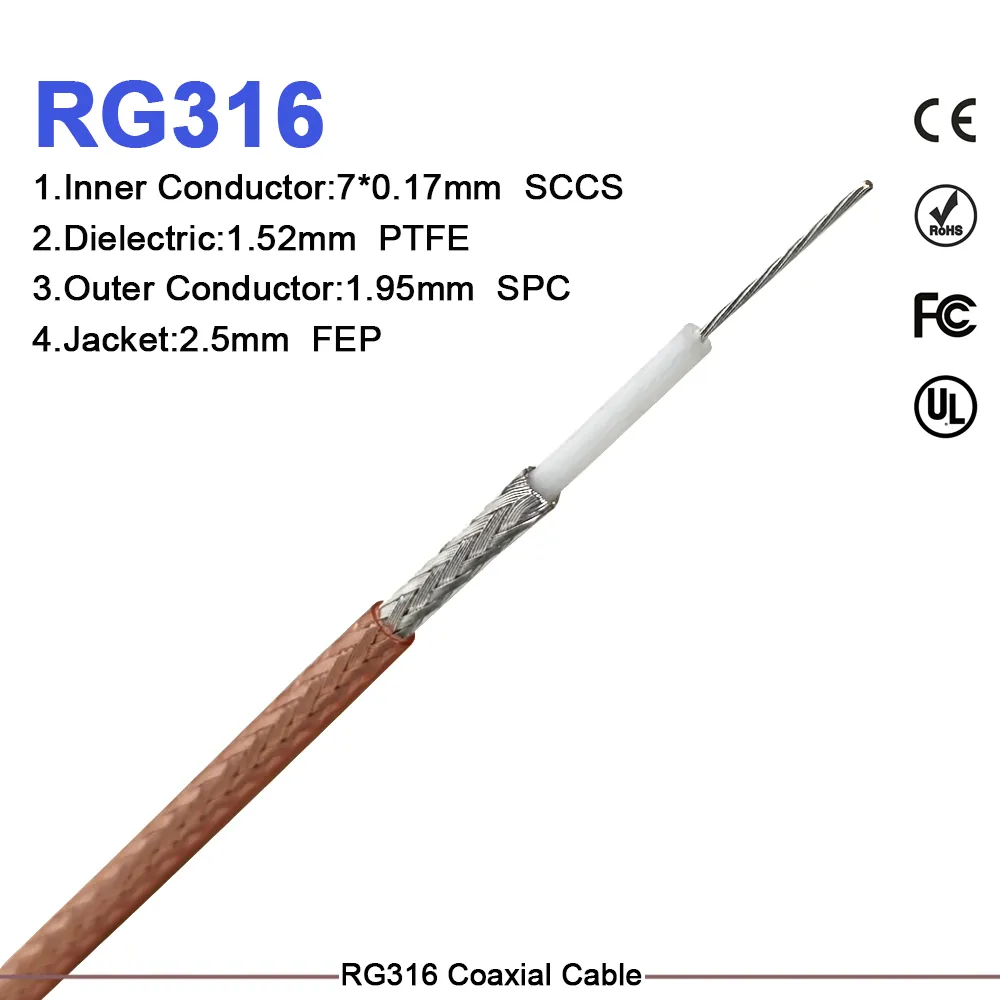
Selecting the right RF interconnect comes down to finding a precise balance between physical constraints, environmental endurance, and high-frequency electrical loss. Compact wireless modules, test benches, and avionics enclosures frequently demand flexible, low-profile cabling that performs reliably under thermal and mechanical stress. The RG-316 coaxial cable serves as an industry standard for these exact demands. This guide explores the mechanical structure, electrical trade-offs, and practical integration tactics for high-density systems, including a side-by-side comparison between the RG-316 coaxial cable and larger options like rg 8x coax.
The inner architecture of the RG-316 coaxial cable is engineered specifically for harsh operating conditions and tight space constraints. Featuring an overall outer diameter of roughly 2.5 mm (0.098 inches), this miniature 50-ohm cable routes smoothly through tight panel openings, complex chassis bays, and crowded PCB interfaces.
Unlike basic consumer coaxial lines built with standard polyethylene (PE) insulation, a high-spec PTFE RF cable uses a fluoropolymer dielectric. Solid polytetrafluoroethylene (PTFE) provides high thermal endurance, maintaining electrical stability from -55°C up to +200°C. Coupled with a silver-plated copper inner conductor and a dense silver-plated copper braid shield, the cable delivers consistent RF transmission up to 3 GHz with strong EMI suppression in noisy environments.
Choosing between an ultra-compact rg316 coax jumper and a mid-sized cable such as rg 8x coax requires reviewing physical dimensions, allowable signal loss, and mechanical routing paths.
| Performance Parameter | RG-316 Coaxial Cable | RG 8x Coax |
|---|---|---|
| Characteristic Impedance | 50 Ω | 50 Ω |
| Max Operating Frequency | 3 GHz | 1 GHz |
| Outer Diameter (OD) | ~2.5 mm (0.098 in) | ~6.1 mm (0.242 in) |
| Nominal Loss @ 1 GHz | ~0.93 dB/m (~28.3 dB/100ft) | ~0.33 dB/m (~10.1 dB/100ft) |
| Nominal Loss @ 2.4 GHz | ~1.46 dB/m (~44.5 dB/100ft) | ~0.55 dB/m (~16.8 dB/100ft) |
| Dielectric Material | Solid PTFE | Foamed PE / PE |
| Minimum Bend Radius | ~12.7 mm (0.5 in) | ~25.4 mm (1.0 in) |
| Temperature Rating | -55°C to +200°C | -40°C to +80°C |
While rg 8x coax yields lower attenuation over extended distances, its bulkier structure makes it impractical for tight cabinet bends or sub-assembly jumpers. An rg316 coax jumper fits easily inside compact enclosures, whereas rg 8x coax fits better on longer, straight feedline runs.
Consider an avionics retrofit requiring an active GNSS antenna connection inside a tight aircraft wing channel. The cable must traverse an 1.8-meter pathway while coping with thermal swings and severe vibration profiles.
In this setup, standard polyethylene cables risk thermal deformation during high-temperature cycles, while thicker options like rg 8x coax exceed maximum bend radius allowances inside structural channels. Deploying a ruggedized PTFE RF cable with high braid density resolves both issues. The low profile passes cleanly through narrow access holes, maintaining structural integrity under vibration testing and keeping VSWR levels below 1.3:1 across GPS L1 and L5 frequencies.
Because small-diameter cables exhibit higher attenuation per unit length, managing signal budgets requires accurate loss calculations.
For internal jumpers under 0.5 meters, total line loss at 2.4 GHz remains under 0.75 dB. However, when routing lengths exceed 2 meters at microwave frequencies, evaluating low-loss alternatives—such as double-shielded RG-142 or semi-rigid assemblies—helps prevent unnecessary link margin degradation.
When specifying a custom RG316 cable assembly for production programs, three critical details keep interconnect systems performing reliably over time:
WORLDPEAK supports these critical RF interconnect demands through precision manufacturing and high-frequency assembly workflows. Utilizing automated crimp termination tools and micron-level CNC machining, WORLDPEAK delivers reliable RG316 cable assembly options, custom PTFE RF cable harnesses, and high-performance connector solutions. Every production run undergoes complete VSWR and insertion loss validation to ensure consistent performance across defense systems, commercial avionics, and advanced wireless infrastructures worldwide.

2026/09/25
Customize an rf high frequency cable for temperature, moisture, corrosion, vibration, flexing, and OEM validation needs.

2026/09/25
Streamline RF equipment assembly lines with custom coaxial jumpers. Reduce line-side rework, ensure precise routing, and boost production efficiency.

2026/09/25
Learn PL-259 connector selection, soldering, weatherproofing, and RF applications for dependable antenna feedlines.

2026/09/25
Confirm impedance for a 90 degree coax connector with an ODM test plan covering VNA setup, VSWR, acceptance criteria, and release records.

2026/09/25
Learn when an n type coax connector can omit extra anti-corrosion treatment and when OEM exposure conditions require it.

2026/09/25
Learn how the custom cable and wire sample process helps ODM buyers validate design, testing, and production readiness.