 EN
EN

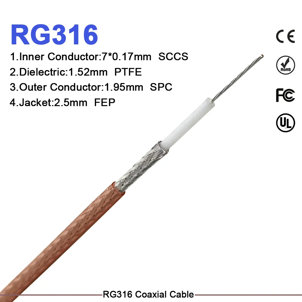
RG-316 PTFE Cable: High-Temp RF Solutions
Working with RF systems that run hot, including automotive electronics, avionics, military field radios, and tight equipment enclosures,you quickly discover that not every coaxial cable holds up under sustained thermal load. Standard PE-jacketed cables shift impedance and soften well before their nominal ratings. In my experience specifying cables for instrumentation setups and compact transmitters, the rg 316 coaxial cable consistently earns its place when thermal and size constraints are non-negotiable. This guide walks through the RG model family, why RG-316's PTFE construction is a different class of cable, how 50Ω and 75Ω impedance choices map to real application domains, and what to look for when sourcing assemblies for both outdoor field work and controlled indoor routing.
The RG Cable Family: Where RG-316 Fits
The "RG" designation originated as a military shorthand for "Radio Guide," and the numbering reflects decades of incremental standardization. Understanding where each model sits helps avoid costly misspecification.
| Type | Impedance | OD (approx.) | Dielectric | Typical Application |
|---|---|---|---|---|
| RG-6 | 75Ω | 6.9 mm | Foam PE | CATV, satellite, CCTV distribution |
| RG-58 | 50Ω | 4.95 mm | Solid PE | Ham radio, legacy Ethernet, lab bench |
| RG-174 | 50Ω | 2.54 mm | PE | Portable RF equipment, GPS receivers, thin patch cables |
| RG-213 | 50Ω | 10.3 mm | PE | High-power HF transmitters, base station feeders |
| RG-316 | 50Ω | 2.49 mm | PTFE | Military, aerospace, medical, high-temp RF links |
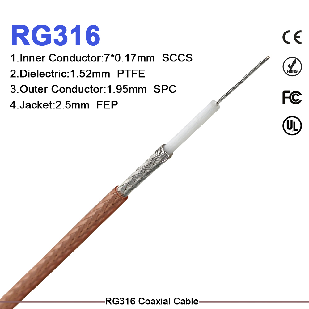
RG-316 and RG-174 are close in diameter—both miniature 50Ω cables—but the materials differ fundamentally. Where RG-174 uses polyethylene insulation and a standard PVC jacket, cable rg 316 pairs a PTFE dielectric with an FEP outer jacket, giving it a 150°C sustained operating range that RG-174 cannot approach. RG-316 is also roughly half the weight of RG-58 for the same run length, which matters in airborne and portable deployments where every gram counts.
PTFE Dielectric: What Changes at High Temperature
The PTFE dielectric layer in rg 316 coaxial cable measures approximately 1.53 mm thick and maintains stable electrical and physical properties up to 150°C in standard versions, with silver-plated copper braid variants reaching 200°C. That is not an incremental difference from PE-based cables, which exhibit measurable dielectric deformation above 75–80°C and can visibly flow under sustained mechanical load near 90°C.
For RF system design, the practical impact is impedance stability across temperature. PTFE's dielectric constant stays consistent where PE shifts, which matters when you're feeding a VCO or a precision attenuator where even a small impedance drift changes the return loss floor. A cable running 10°C above its real thermal limit will shift, and that shift often appears as an unexplained calibration offset traced to the cable run rather than the instrument.
The center conductor in RG-316 is a 26 AWG stranded silver-plated copper core. Silver plating reduces skin-effect resistance at higher frequencies. Capacitance runs at approximately 29.4 pF/ft (96.5 pF/m) at 50Ω impedance. One thing that sometimes trips up engineers: cable loss at DC tells you almost nothing useful about behavior at your operating frequency. RG-316 attenuation is roughly 0.6–0.7 dB/m at 1 GHz and climbs past 1.2 dB/m at 3 GHz: these are the numbers that belong in your link budget.
50Ω vs. 75Ω: Choosing the Right Impedance
The RG cable family splits cleanly along impedance lines, and the selection rationale is well established.
50Ω systems dominate RF communications, test equipment, radar, and most commercial wireless infrastructure. SMA, N-type, BNC, and TNC connectors are predominantly 50Ω. Military and aerospace RF links are essentially all 50Ω. If you are sourcing rg 316 coaxial cable for a transmitter, spectrum analyzer feed, or base station antenna run, you are in 50Ω territory, and rg 316 covers this domain across all standard connector families.
75Ω systems are the domain of video distribution, broadcast infrastructure, CATV, and satellite LNB feeds—applications where minimum attenuation at baseband video frequencies matters more than power handling. RG-6 is the standard bearer. There is no standard 75Ω variant of RG-316; that combination does not exist as an RG designation. If a procurement request calls for a 75Ω PTFE miniature cable for a video link inside a hot enclosure, that is a custom specification, not a standard RG type. Worth clarifying early in the sourcing process.
The rg 316 u Designation: What Changes
The "/U" suffix in rg 316 u—formally RG-316/U—indicates conformance to MIL-C-17 structure requirements defining conductor, dielectric, shield, and jacket materials. In practical sourcing terms, it signals UV resistance, water resistance, oil and chemical resistance in the outer jacket, and in many production runs, a halogen-free flame-retardant formulation. The military designation M17/113-RG316 is the formal procurement reference used in defense and government contract documentation.
For outdoor deployments or installations near coolants and solvents, the rg 316 u specification is the correct reference. One installation reality: the cable jacket being chemical-resistant does not mean the connector interface is automatically weatherproof. Applying self-amalgamating tape or a weatherproofing boot to each outdoor connector termination is a separate step, and skipping it is a common reason field assemblies fail at the connector rather than the cable body.
Custom Assemblies: Lengths, Connectors, and Jacket Options
Pre-terminated assemblies eliminate field termination variability and allow incoming inspection to verify electrical length and insertion loss before installation. Worldpeak's Worldpeak RG316 Pre-Terminated Cable Assembly supports custom connector combinations across SMA, SMB, BNC, TNC, and MCX interfaces, with mixed-gender configurations for system integrators matching a specific panel layout. Each assembly ships with swept insertion loss and VSWR test data for direct entry into as-built records.
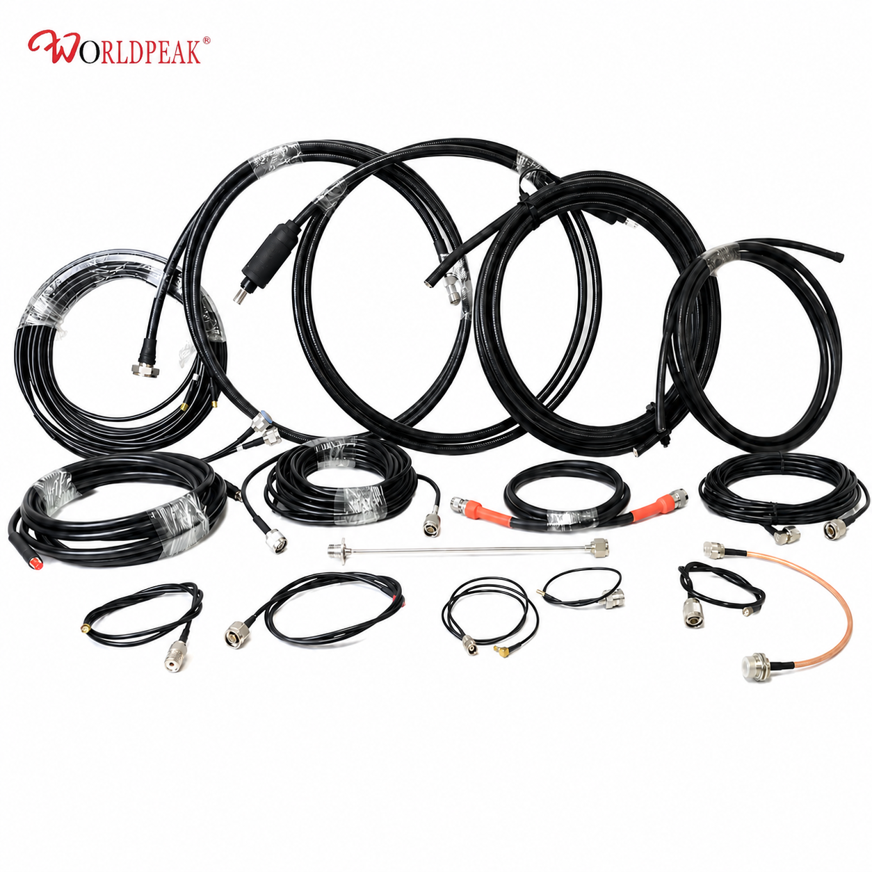
For pre-order engineering review, the Worldpeak RG316 50-Ohm Coaxial Cable: Engineering Data & Selection Guide provides construction parameters and loss tables by frequency to support system-level specification matching. Custom jacket colors, non-standard lengths to millimeter tolerance, and specific shield coverage percentages are available through direct inquiry.
Field Installation and Indoor Wiring: Practical Guidelines
RG-316's small diameter and flexibility ease routing, but the minimum bend radius still applies—approximately 6–7 mm for a static single bend, with a more conservative radius required for any application involving repeated movement. Service loops and robotic arm runs should use a larger radius than the datasheet minimum; choosing cable flexibility over absolute minimum loss in that context is the right trade-off for mechanical life.
Outdoor field construction:
- Secure runs every 30–50 cm with UV-stable clamps; unsupported spans vibrate in wind and accelerate jacket wear at contact points.
- Apply weatherproofing at all outdoor connector interfaces, working from the cable end toward the connector body to prevent water ingress at the seam.
- Use grommets or cable bushings where cable enters conduit to prevent jacket abrasion at the conduit edge.
- Leave a service loop of at least 30 cm at each equipment connection point for future re-termination.
Indoor rack and chassis wiring:
- Route rg 316 cable away from power supply exhaust and high-current busbars—even PTFE cable benefits from operating below its thermal ceiling continuously.
- Label both ends of any run longer than 50 cm; RF cable troubleshooting in dense wiring without traceability documentation is avoidable.
- Avoid sharp 90-degree bends at duct corners; radius cable paths to stay above the minimum bend specification.
- Torque connector interfaces to specification; under-torqued connectors are a common source of intermittent VSWR degradation that is difficult to reproduce on the bench.
For installations involving crew members with varying termination experience, factory-terminated assemblies are the most reliable path to consistent electrical performance. Impedance discontinuities from hand-termination inconsistency appear as return loss anomalies that can be confused with downstream impedance problems until the connector interface is carefully inspected.





