 EN
EN

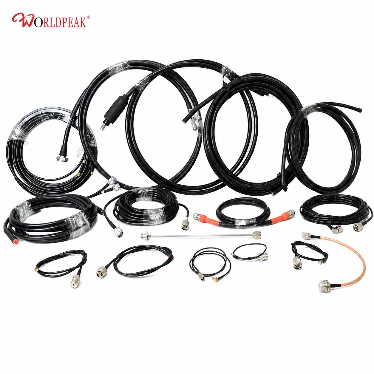
RG-316 PTFE Coaxial: Ideal for Microwave Links
As an RF systems engineer who has designed point-to-point microwave deployments and bench test setups, I have learned that coaxial cable choice often determines whether a signal chain holds margin or quietly degrades it. With so many RG designations available — rg316 rg cable, RG58, RG174, RG213, and RG6 among them — the question I encounter most is which one fits a given microwave application and why the choice matters at operating frequencies above 1 GHz.
This article works through the RG cable family, explains where RG316 coaxial fits in the impedance and frequency landscape relative to alternatives like rg 178 and rg 58a u, and gives practical guidance for connector selection, custom assembly options, and installation in field and indoor environments.
The RG Cable Family: Model Designations and What They Tell You
The "RG" designation originated in military radio guide specifications. Each number corresponds to a defined cable construction: conductor size, dielectric material, shield type, and impedance. Here is a working overview of commonly specified cables:
| Cable Type | Impedance | Dielectric | Outer Diameter | Primary Applications |
|---|---|---|---|---|
| RG6 | 75 Ω | Foam PE | ~6.9 mm | Cable TV, satellite, CATV distribution |
| rg 58a u | 50 Ω | Solid PE | ~5.0 mm | Amateur radio, legacy Ethernet, general RF patching |
| RG174 / rg 178 | 50 Ω | Solid PE | 1.8–2.8 mm | Portable equipment, GPS, compact internal wiring |
| RG213 | 50 Ω | Solid PE | ~10.3 mm | High-power amateur radio, base station feeder runs |
| RG316 / rg316 rg cable | 50 Ω | PTFE | ~2.5 mm | Microwave links, test equipment, military, aerospace |
The key difference that sets RG316 rg cable apart from rg 58a u or rg 178 is the dielectric material. Early in my work with RF cable selection, I optimized for insertion loss per meter alone. The blind spot was dielectric type: when a cable operates above 2 GHz continuously or routes through a high-temperature enclosure, the dielectric becomes the independent constraint that a simple loss-per-meter figure cannot capture.
Why PTFE Makes RG316 Right for Microwave
RG316 uses PTFE (polytetrafluoroethylene) dielectric rather than the polyethylene found in rg 58a u or rg 178. That difference shows up clearly at microwave frequencies:
- Temperature stability: PTFE maintains consistent dielectric properties to approximately 150 °C, compared to roughly 80–85 °C for PE-based cables including rg 58a u. For cables routed near heat sources or used in outdoor enclosures in warm climates, that margin is directly relevant.
- Lower dielectric loss at microwave frequencies: PTFE has a lower loss tangent than polyethylene above 1 GHz, reducing signal attenuation per meter where rg 178 and rg 58a u show measurable degradation.
- Chemical and UV resistance: The FEP outer jacket on RG316 rg cable resists fuel, oils, and UV — relevant for outdoor tower and rooftop installations where standard PVC jackets degrade within a few seasons.
Physically, RG316 is built with a silver-plated copper inner conductor (7 × 0.175 mm), surrounded by a PTFE dielectric layer (~1.53 mm), a silver-plated copper braid shield (~1.95 mm), and an FEP jacket bringing total outside diameter to ~2.5 mm. Military designation is M17/113-RG316; the civilian designator RG316/U confirms the 50 Ω impedance standard. Impedance: 50 ± 2 Ω; temperature rating: up to 150°C; minimum bend radius: ~15 mm.
50 Ω vs. 75 Ω: Choosing the Right Impedance
If your primary constraint is signal integrity in an RF transmission system — wireless infrastructure, test and measurement, military radio — then 50 Ω should carry the most weight. If the application is video distribution or satellite reception over long runs, 75 Ω is the correct standard.
RG316 rg cable is a 50 Ω cable, fitting these applications:
- Point-to-point microwave radio links (2–18 GHz range)
- Laboratory test bench RF connections and instrument cabling
- Military and aerospace avionics wiring
- Medical imaging equipment RF interconnects
- Compact embedded RF modules where rg 178 is too high-loss above 2 GHz
Mismatching impedance at cable interfaces introduces reflections that degrade link margin across affected frequencies. Roughly speaking, at 6 GHz each uncompensated mismatch reflection can contribute 0.1 to 0.5 dB to return loss degradation — a ballpark estimate that illustrates why the impedance choice warrants early attention in system design.
RG6 (75 Ω) is correct for CATV, satellite dish feedlines, and broadcast distribution where source and load are already designed around 75 Ω. Mixing a 50 Ω rg316 rg cable into a 75 Ω distribution system degrades return loss performance at every affected interface.
Custom Assembly Options for RG316 Coaxial
Standard off-the-shelf RG316 lengths work for many bench and prototype applications. System integrators designing production equipment or field-deployed infrastructure frequently need assemblies matched to exact routing geometries, specific connector combinations, or application-specific jacket requirements.
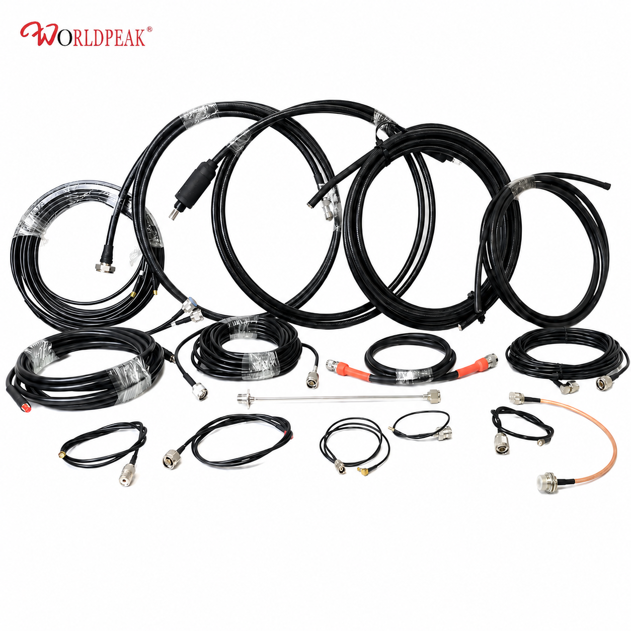
Worldpeak manufactures RG316 50-Ohm Coaxial Cable to non-standard lengths with selectable connector terminations. For applications requiring a ready-to-install assembly, the Worldpeak RG316 Pre-Terminated Cable Assembly ships with pre-inspected connector interfaces and test documentation for incoming inspection.
Key custom options when placing an RFQ for rg316 rg cable:
- Length: Match routing paths precisely. At 2.4 GHz, RG316 coaxial loses approximately 1.46 dB per meter — a rough ballpark figure showing why short runs matter at microwave frequencies.
- Connector interface: Common terminations include SMA, RP-SMA, BNC, MCX, and MMCX. Specify gender at both ends explicitly.
- Double shielding (RG316DS): For high-EMI environments where single-braid coverage is insufficient, an RG316DS variant adds a second braid layer.
- Jacket options: Standard FEP suits most applications; additional colors or flame-retardant variants are available for installations with marking or fire-safety requirements.
Installation Guidance: Field and Indoor Environments
RG316's minimum bend radius is approximately 15 mm. Cables routed through cable trays or tower mounts are routinely bent tighter than specification during installation, introducing micro-cracking in the braid that only manifests as elevated return loss weeks or months later.
Outdoor and field installations:
- Maintain bend radius compliance at all routing corners; use cable guides at structural edges.
- Weatherproof all connector interfaces with self-amalgamating tape applied in two layers, starting at the connector body and extending onto the cable jacket.
- Secure cables with saddle clamps; unsupported vertical runs allow cable weight to cold-flow the jacket at the clamp point over time.
Indoor rack and equipment wiring:
- Plan cable routing geometry before cutting to length. The 2.5 mm diameter of RG316 rg cable suits tight chassis routing, but routing path validation prevents costly re-terminations.
- Torque SMA connectors to specification (typically 3–5 in-lb). Under-torqued SMA connectors are a leading cause of intermittent insertion loss after thermal cycling.
- Label each assembly at both ends with cable type, connector interface, and assembly ID before routing.
If the installation environment stays below 85 °C with low humidity, rg 178 or rg 58a u assemblies may perform adequately for short internal runs at frequencies below 1 GHz. Once either temperature or frequency requirements push beyond that range, RG316's PTFE construction provides the stability margin that PE-based alternatives cannot match.
Summary: Selecting the Right RG Cable for Microwave
The decision across RG cable types depends on three constraints working simultaneously: operating frequency, temperature environment, and physical routing geometry. RG316 rg cable addresses frequency and temperature requirements in a 2.5 mm diameter cable that still routes through tight enclosures and meets microwave link demands from 1 to 18 GHz. For applications where rg 58a u or rg 178 reach their practical limits — high frequency, high temperature, or demanding outdoor environments — RG316 coaxial with PTFE dielectric is the specification-matched choice.





