 EN
EN

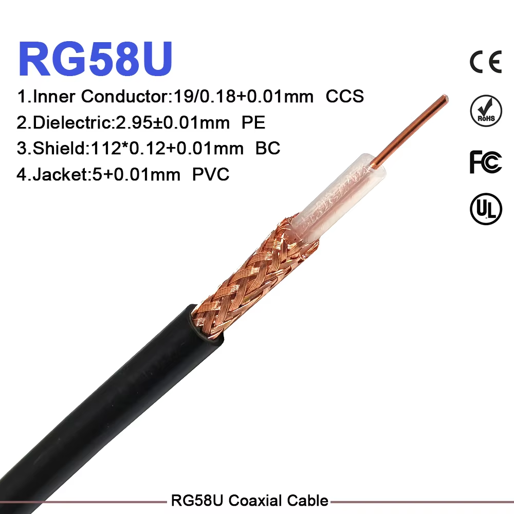
An rg58 rf cable is routinely summarized with a single headline specification: 50 ohms. While that nominal impedance rating is essential, it leaves out critical answers that design engineers and system installers need most: how much signal frequency and power can this assembly safely transmit over a specific distance?
The practical answer depends entirely on operational context. Conductor construction, total run length, target operating frequency, antenna mismatch, connector quality, routing tight spots, and ambient enclosure temperatures all shape real-world performance.
Assuming a single universal power limit applies across every installation scenario is a common design trap. A short bench lead operating at modest frequencies performs reliably, whereas the same cable routed through a warm equipment rack at UHF frequencies generates significant thermal loss, degrading link performance.
Frequency Attenuation Drives Real-World Power Capacity
The rg58 rf cable family encompasses flexible 50-ohm coaxial lines, but published attenuation figures vary based on center conductor stranded count, dielectric composition, shielding braid density, and jacket materials. Always rely on official datasheets for exact calculations.
As a representative industry benchmark, standard rg58 cable exhibits approximately 3.3 dB of attenuation per 100 feet at 50 MHz, which rises sharply to 10.6 dB per 100 feet at 450 MHz, and reaches nearly 21.5 dB per 100 feet at 1 GHz. Signal loss increases progressively with higher frequencies and linearly with cable length.
This exponential rise in attenuation directly impacts power handling:
-
Energy Dissipation: If 100 Watts of RF power enters an rg58 rf cable run with 3 dB of total insertion loss, roughly half the power (50 Watts) reaches the load while the remaining half converts into heat along the cable body.
-
Thermal Accumulation: Operating inside enclosed pathways or high-ambient-temperature environments prevents heat dissipation, raising internal dielectric temperatures and risking premature cable breakdown.
-
Reduced Link Headroom: Beyond thermal safety concerns, excessive insertion loss starves the receiving antenna or instrument of necessary signal margin.
Essential Checklist for Real-World Power Verification
Determining usable RF power capacity requires looking beyond simple datasheet maximums:
-
Calculate Insertion Loss at Frequency: Determine exact line loss at target operating frequencies for the completed assembly length, including connector transition allowances.
-
Factor VSWR and Reflected Power: Antenna impedance mismatches create voltage standing waves that elevate localized current peaks along the line.
-
Assess Ambient Thermal Environment: Cables bundled tightly inside industrial conduits or exposed to direct sunlight shed thermal energy far less effectively than lines in open air.
-
Evaluate Transmission Duty Cycle: Continuous carrier modes and high-average-power modulations require greater thermal headroom than brief intermittent test bursts.
-
Match Connector Ratings: The overall assembly is only as strong as its weakest link, including interface type, termination crimp quality, and strain relief.
Selecting Coaxial Options Based on Design Constraints
Choosing between popular 50-ohm flexible options requires matching cable attributes to physical installation priorities:
-
General-Purpose Flexibility: Standard rg58 cable provides an economical balance of mechanical flexibility and power capacity for short-to-medium interconnects at moderate frequencies.
-
Compact Internal Routing: An rg 174 cable features a significantly smaller outer diameter, making it ideal for tight chassis routing, micro-pigtails, and space-constrained modules. However, its small conductor size carries a higher loss penalty per meter.
-
High-Temperature Environments: An rg 400 coax cable utilizes double-shielded construction and a fluoropolymer jacket, providing superior temperature tolerance, high shielding effectiveness, and mechanical durability for demanding industrial applications.
Comparing delivered power and receiver sensitivity across options yields a much clearer engineering picture than evaluating catalog power ratings in isolation.
Proper Assembly and Termination Practices
Even the highest-grade cable underperforms when terminated poorly. Preserving signal integrity requires careful assembly execution:
-
Preserve Internal Geometry: Stripping tools must cut clean boundaries without nicking the center conductor or crushing the dielectric insulator.
-
Control Bend Radii: Avoid sharp 90-degree bends immediately behind the connector ferrule. Use protective strain relief boots to prevent center conductor fatigue from repeated motion.
-
Select Matched Connectors: Ensure connector pin dimensions and ferrule hex sizes match the exact cable geometry.
Custom Cable Lengths and Environmental Considerations
Specifying exact assembly lengths eliminates excess coiled cable that adds unnecessary path attenuation. For indoor installations, keep cable runs away from sharp enclosure edges, pinch points, and hot power supplies.
Outdoor runs demand UV-resistant jacketing, proper strain relief supports to prevent cable weight from loading connector interfaces, and self-amalgamating weatherproofing tape over exposed metal couplings. Standard indoor rg58 cable jackets should never be used in outdoor installations exposed to standing water or extreme temperature cycling.
Key Procurement Considerations for Project Engineering
When is an RG58 RF cable the right choice?
An rg58 rf cable is ideal for short-to-medium 50-ohm interconnects where frequency-specific attenuation and ambient thermal conditions fall comfortably within system loss budgets.
When should an RG174 cable be specified?
Choose an rg 174 cable when ultra-compact chassis routing is the governing constraint and the overall loss budget supports higher attenuation per meter.
When does an RG400 coax cable make sense?
An rg 400 coax cable is worth the upgrade when high operational temperatures, high-density EMI environments, or aggressive mechanical conditions dictate double-shielded fluoropolymer construction.
Streamlining RF Systems with Precision Manufacturing
Building reliable wireless networks requires sourcing coaxial components and custom assemblies from manufacturing partners who enforce strict quality control, precise impedance matching, and reliable global supply chains. Inconsistent dielectric dimensions or poor ferrule crimping degrade return loss and inflate path loss.
Worldpeak delivers precision-engineered rg58 rf cable assemblies, compact rg 174 cable pigtails, high-temperature rg 400 coax cable assemblies, and custom interconnect hardware for commercial, industrial, and broadcast applications globally. Supported by automated stripping and crimping machinery, rigorous VSWR testing, and complete batch traceability, Worldpeak provides dependable 50-ohm solutions designed for demanding deployments.
Whether your next build requires bulk rg58 cable spools, custom jumper leads, or specialized high-temperature assemblies, partnering with Worldpeak keeps network infrastructure projects moving forward on schedule.
Frequently Asked Questions
What is the maximum usable frequency for an RG58 RF cable?
While an rg58 rf cable can physically transmit signals up to 1 GHz or higher, attenuation increases significantly above 400 MHz. For high-frequency runs over long distances, lower-loss 400-series cable options are recommended.
Why does an RG174 cable exhibit higher signal loss than an RG58 cable?
An rg 174 cable utilizes a much smaller center conductor and dielectric core than an rg58 cable. Smaller conductor surface area increases skin effect resistance, resulting in higher attenuation per meter.
What makes RG400 coax cable suitable for high-temperature applications?
An rg 400 coax cable incorporates FEP (fluorinated ethylene propylene) jacketing and PTFE dielectric insulation, allowing it to withstand operating temperatures from -55°C to +200°C while offering double-braid shielding against EMI.





