 EN
EN

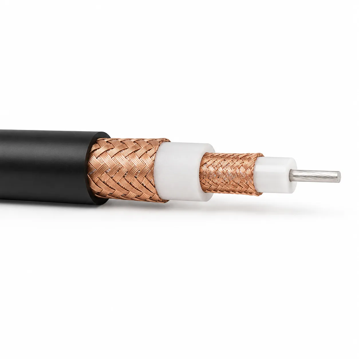
Right Angle Coax Connector: Benefits and Installation
When system integrators first encounter right angle coax connectors, a common assumption is that they are electrically equivalent to straight connectors with a 90-degree cable bend added externally. In my experience designing RF signal paths for rack-mounted and panel-integrated systems, that assumption creates problems precisely at the frequencies where performance margins matter most. A right angle coax connector is not simply a straight connector bent at 90 degrees — the inner conductor path geometry through the angle transition differs, and VSWR performance at frequencies above 6 GHz must be verified independently for the right angle variant.
Why the Right Angle Form Factor Exists
The fundamental installation problem that right angle coax connectors solve is cable routing in constrained geometry. When a connector port faces directly toward a panel or chassis wall, a straight connector forces the cable away from the surface and then requires a manual bend back toward the routing path. That bend introduces mechanical stress at the cable's outer conductor and can deform the dielectric enough to shift characteristic impedance at the bend point.
For a professional RF signal chain operating at 3 GHz or above, the mechanical stress at a forced cable bend translates directly into a measurable impedance discontinuity — visible in your return loss sweep as elevated VSWR at consistent frequency intervals.
Interface Standards and Compatibility
Choosing the right right angle coax connector begins with the interface standard. The four most common in system integration and repair work are:
- SMA: 50 Ohm, DC to 18 GHz standard range. SMA right angle adapters are common in compact RF enclosures and PCB-adjacent routing. An sma right angle adapter serves both direction-change and interface-conversion roles when port and cable termination differ.
- BNC: DC to 4 GHz standard. Right angle BNC connectors appear in test and measurement setups, security systems, and video equipment where the bayonet lock and right angle geometry simplify panel cable management.
- N-type: DC to 11–18 GHz. Used in outdoor base station feeders and high-power RF installations where the threaded coupling provides mechanical security under vibration.
- F-type: Consumer video and cable TV only. Not suited for professional RF chains above 1 GHz.
For mixed-interface infrastructure, an sma right angle adapter bridges the connector standard at the direction-change point, while a right angle bnc serves lower-frequency test connections. When cable and port interfaces differ, an sma to coax adapter can resolve the mismatch without re-terminating the cable — provided it is rated for your operating frequency and maintains 50 Ohm impedance through the conversion.
Straight, Right Angle, and Panel Mount: Installation Form Comparison
| Form | Typical Application | Key Consideration |
|---|---|---|
| Straight | Inline connections, open-frame racks, cable with ample clearance | Minimal impedance disturbance; simplest signal path |
| Right Angle | Tight enclosures, PCB-adjacent ports, panel-facing installations | Verify VSWR at operating frequency; alignment before torque is critical |
| Panel Mount | Bulkhead through-wall connections, chassis-integrated ports | Adds a fixed impedance reference at the enclosure wall |
Below 3 GHz with adequate cable clearance, a straight connector keeps the signal path simple. In tight chassis geometry, the right angle form removes the cable stress point and stabilizes the assembly under vibration. Panel mount adds a bulkhead reference that decouples internal and external cable runs.
Impedance Matching and High-Frequency Performance
At 10 GHz, even a short impedance discontinuity through a connector body creates a measurable reflection. A well-designed right angle connector maintains 50 Ohm impedance through the angle transition by controlling the inner conductor geometry and dielectric distribution. A connector that achieves this at 6 GHz may not do so at 12 GHz — which is why procurement specifications for high-frequency right angle connectors should include VSWR data at the upper end of the intended band.
I expected the right angle connector to be the weak point in an assembly I measured at 12 GHz. What the measurement showed instead was that the connector performed to spec; elevated return loss was coming from a cable bend immediately behind the angle body. The connector's impedance-controlled transition performs as intended only when the cable exits cleanly.
Cables paired with right angle connectors need consistent impedance across the full run. The LMR400 Low-Loss 50 Ohm Coaxial Cable provides a matched 50 Ohm interface for the right angle transition. Pre-terminated options like the Worldpeak RG316 TriCoax Pre-Terminated Cable Assembly remove field assembly variables. For space-constrained applications, the Worldpeak RG196 50-Ohm Coaxial Cable offers engineering-grade specifications for precision right angle configurations.
Installation Guidelines
Angle alignment before tightening is the installation variable that most commonly degrades performance in right angle coax connectors. The right angle body has a rotational degree of freedom that straight connectors lack — torquing to specification leaves the body free to point in a direction that places lateral stress on the cable. Two technicians working from the same torque spec but different alignment habits will produce measurably different VSWR results at 5 GHz.
Before final torque, confirm the right angle body points in the intended routing direction and that the cable exits without a secondary bend. Do not use the cable to resist body rotation during installation. After installation, a brief insertion loss and return loss sweep confirms whether mating and alignment produced expected performance. Elevated return loss at a consistent frequency pattern indicates a connector mating issue or alignment offset — check this before suspecting the cable.
Selection Reference for System Integrators and Repair Engineers
Key selection criteria for right angle coax connectors:
- Interface standard: Match the body interface (SMA, BNC, N-type, F-type) to both port and cable. Mixed-interface scenarios require a type-converting adapter at the angle body.
- Frequency range: Confirm the right angle variant's VSWR specification at your operating frequency — the straight version's spec does not automatically transfer.
- Impedance continuity: Verify the right angle body maintains 50 Ohm through the angle transition, not only at the mating interface.
- Installation form: Right angle for clearance-constrained routing; panel mount for a fixed bulkhead reference.
- Cable compatibility: Pair with a cable whose impedance and shielding match the connector's design intent.
System integrators procuring across SMA, BNC, and N-type families — including right angle variants — can source the full interface range from Worldpeak, whose RF connector and cable assembly coverage extends from DC to 18 GHz. Right angle configurations include impedance-controlled angle transition geometry suited to high-frequency applications.





