 EN
EN

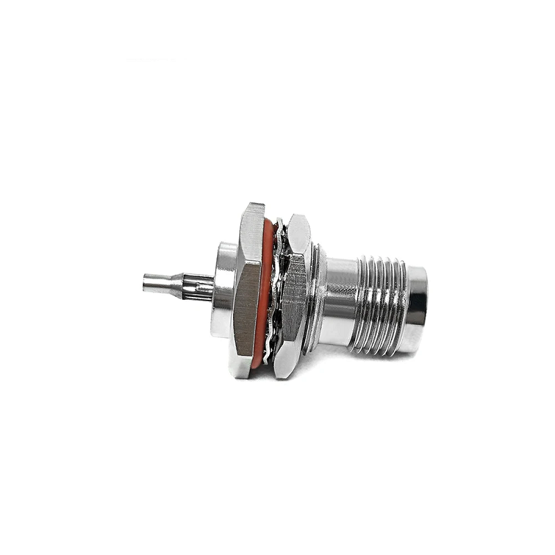
Finding the right radio frequency component often feels straightforward until two parts look identical on the outside but refuse to work together on the inside. That exact scenario plays out every day with the RP TNC interface. Mechanics and technicians frequently order what looks like a standard coaxial threaded coupling, only to discover during installation that signal transmission fails entirely—or worse, fragile center pins end up crushed.
Understanding how an RP TNC connector behaves, why its design exists, and how to verify interface gender before placing a purchase order saves both project budgets and field installation timelines.
Standard TNC vs. RP-TNC: What Reverse Polarity Really Means
The term "reverse polarity" causes endless confusion in RF hardware engineering. It sounds like an electrical warning about DC voltage or ground loops, but it actually describes a purely mechanical swap inside the connector housing.
The outer threaded shell of a reverse polarity design remains completely identical to a standard TNC fitting. The change happens exclusively at the dielectric face:
-
Standard TNC Pinout: A male plug features internal threads and a solid center pin. A female jack features external threads and a hollow receptacle socket.
-
Reverse Polarity Pinout: A male plug keeps internal threads but swaps the center contact to a hollow socket. A female jack keeps external threads but houses a solid center pin.
Because the outer threads match perfectly between standard and reverse-polarity versions, two opposing types will happily thread together. However, mating a standard male pin with a reverse-polarity female pin pushes two solid metal contacts directly into each other, damaging the gold plating and destroying the interface dielectric.
The Naming Confusion Behind the RP TNC Female Interface
Connector terminology usually links housing gender directly to contact gender. In standard RF hardware, "female" means external body threads and an inner socket. Reverse polarity breaks this visual rule, creating a frequent trap for purchasing teams.
An RP TNC female component presents external threads on the outside shell, leading many buyers to assume it accepts a male pin. In reality, that same interface houses a male center pin inside the insulator.
When requesting replacement leads or specifying bulkheads for outdoor wireless hardware, relying on verbal descriptions like "female connector" almost guarantees ordering mistakes. Engineering teams should always confirm pin configurations using dimensional drawings or direct visual inspection under clean lighting rather than relying on quick visual assumptions.
Five Practical Steps for Interface Verification
Before sending out a bill of materials or finalizing a custom cable assembly order, run through this practical checklist to ensure physical and signal compatibility:
-
Confirm Interface Family: Check that the equipment port is a true TNC thread, not an N-type, SMA, or BNC barrel with similar dimensions.
-
Inspect the Outer Housing: Determine whether the mounting location needs external threads or an internal coupling nut.
-
Verify Center Pin Configuration: Look straight into the connector face. Identify whether the application calls for a solid center pin or a hollow receptacle.
-
Check System Impedance: Ensure all joined components share the same impedance rating—typically 50 Ohms for wireless networking and telemetry, or 75 Ohms for specialized video signals.
-
Review Environmental Demands: Factor in outer cable diameter, strain relief boots, IP-rated weather seals, and minimum bend radius constraints.
Why Threaded Interconnects Handle High Vibration Applications
Push-on interfaces like SMB or twist-lock options like BNC serve bench testing well, but rugged deployments require continuous mechanical engagement. Threaded connector bodies excel in challenging operational environments because screw threads resist backing off under constant motion.
Commercial wireless gear relies heavily on these threaded configurations across demanding applications:
-
Outdoor industrial Wi-Fi access points and long-range mesh nodes
-
Vehicle telemetry units, fleet management hardware, and GNSS trackers
-
Aerospace payloads, drone communications, and marine navigation arrays
Beyond mechanical stability, maintaining low signal loss across high frequencies depends on proper installation technique. Overtightening a coupling nut deforms internal contact surfaces, while under-torquing leaves microscopic gaps that degrade return loss. Using calibrated torque wrenches and maintaining clean dielectric faces ensures stable performance up to 6 GHz and beyond.
Selecting Form Factors for Custom Hardware Builds
Right-Angle Configurations
Space constraints inside tight radio enclosures often prevent straight cable exits. A right-angle body solves tight bend issues behind mounting plates and antenna arrays. Because internal right-angle transitions introduce slight electrical discontinuities, engineers should verify insertion loss ratings at target operating frequencies rather than assuming performance matches straight versions.
Panel Mount Solutions
A TNC panel mount connector creates a clean, serviceable pass-through across enclosure walls. Selecting the right panel jack requires evaluating wall thickness, cutout geometry (such as D-flat shapes that prevent body rotation during tightening), rear-side solder or crimp terminations, and weatherproofing gaskets.
RF Cable Assemblies and Adapters
Adapters provide quick bridge connections between legacy radio ports and modern antenna leads. However, every extra adapter interface introduces roughly 0.1 to 0.3 dB of signal attenuation and adds another potential mechanical failure point. Keep adapter chains as short as possible, and clearly specify both ends using complete industry terminology—such as specifying an RP-TNC plug to N-type jack transition—to prevent shipment errors.
Streamlining RF Component Procurement
Sourcing reliable RF interconnects requires working with manufacturers who understand both strict tolerances and steady supply chain demands. High-frequency communication networks leave zero room for inconsistent plating thickness, poor dielectric materials, or imprecise contact alignment.
As a dedicated RF hardware supplier, CNRF Connectors provides precision-engineered coaxial adapters, custom cable assemblies, and specialized interface solutions for global industrial and wireless markets. CNRF Connectors supports system integrators, OEM manufacturers, and field engineering teams with comprehensive technical evaluations, custom manufacturing capabilities, and dependable factory direct supply chains.
Whether your next build demands a high-volume supply of standard coaxial assemblies or specialized TNC panel mount connector configurations, reviewing interface specifications before production prevents field rework and keeps infrastructure deployments on schedule.
Frequently Asked Questions
Why was reverse polarity hardware created in the first place?
Regulatory agencies originally mandated reverse polarity interfaces on commercial Wi-Fi hardware to prevent consumers from attaching high-gain, non-compliant antennas to unlicensed transmitters. Over time, reverse polarity designs became the industry standard across sub-6 GHz wireless hardware.
Can a standard TNC adapter connect directly to a reverse polarity port?
No. Although the outer screw threads will engage smoothly, the center contact pin configurations do not match. Attempting to force them together results in an open circuit or permanent pin deformation. Always use a dedicated adapter designed specifically to transition between standard and reverse-polarity interfaces.
What frequency range do these connectors typically support?
Quality brass or stainless steel variants comfortably handle frequencies from DC up to 6 GHz or 8 GHz, making them well-suited for Wi-Fi 6, cellular IoT, sub-6 GHz 5G, and satellite positioning systems. Always check specific manufacturer data sheets for exact voltage standing wave ratio limits across your intended frequency band.





