 EN
EN

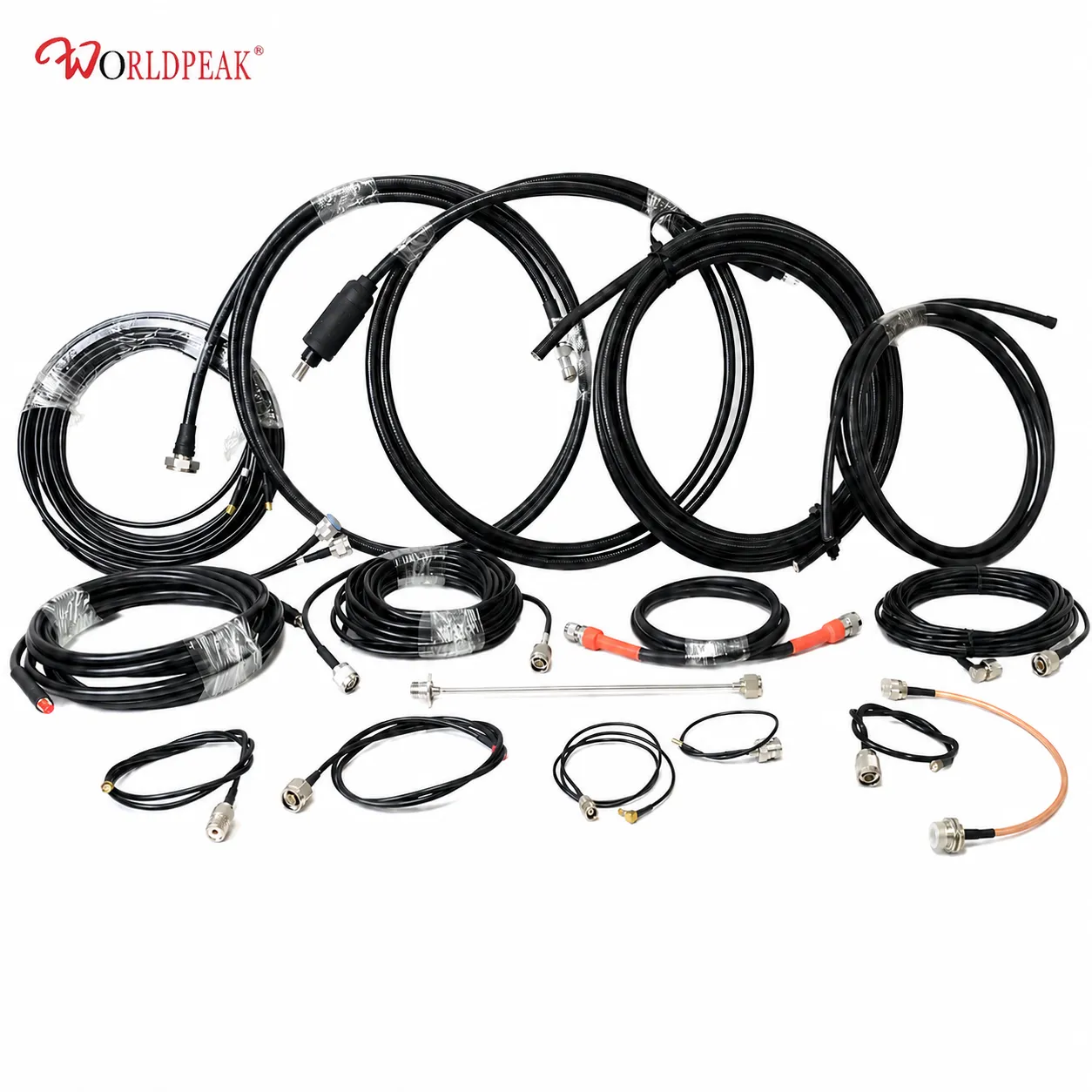
SMA Coaxial Cable Assembly: Specs, Types and Uses
Spend enough time specifying RF interconnects for telecom infrastructure and you develop a sharper appreciation for the variation within a product category as seemingly simple as an SMA coaxial cable assembly. The connector interface is standardized, the impedance is standardized — and yet performance can differ by a factor of two or three, depending on the cable, termination method, and bend radius constraints of your installation.
This guide covers the core specifications, the cable types most commonly paired with SMA connectors, typical use cases, and the handling details that determine whether an assembly delivers its rated performance in a deployed system.
What Is an SMA Coaxial Cable Assembly?
An SMA coaxial cable assembly combines a length of coaxial cable with SMA connectors pre-terminated at one or both ends. SMA (SubMiniature version A) is a semi-precision threaded interface developed in the 1960s and now among the most widely used RF connector types across telecom, instrumentation, and embedded wireless applications.
The defining electrical characteristic is its 50-ohm characteristic impedance, matching the source impedance of most RF signal chains. The threaded coupling mechanism provides a more stable mating interface than push-on alternatives, suitable for both bench setups and permanently installed infrastructure.
Key Electrical Specifications
Before selecting a specific sma coaxial cable assembly configuration, it helps to understand the specification parameters that will govern its usability in your application.
Frequency Range
Standard SMA connectors are rated DC to 18 GHz. Some precision variants reach 26.5 GHz, with tighter dimensional tolerances. For most telecom applications (5G small cells, WLAN access points, microwave backhaul) the 18 GHz ceiling is sufficient.
Impedance: 50 Ω vs 75 Ω
The SMA interface is inherently a 50-ohm standard. This matters when specifying cable: if you source a 75-ohm coaxial cable — common in video distribution and cable television infrastructure — and terminate it with SMA connectors, the impedance mismatch at each interface generates reflections that degrade signal quality. The VSWR at the connector interface is typically ≤1.3:1 for quality SMA assemblies at frequencies below a few GHz. Introducing a 75-ohm cable into a 50-ohm system will measurably worsen this figure.
If you are sourcing cable for an SMA coaxial cable assembly in a standard RF system, specify 50-ohm cable. The 75-ohm type appears in SMA-terminated assemblies only in test setups deliberately characterizing impedance mismatch, not in production installations.
Attenuation
At 1 GHz, LMR-400 loses approximately 1.5 dB per 100 feet versus RG-58's 3.9 dB, about 2.6 times more loss. For runs under a meter the difference is often acceptable; for feeder runs of 3 meters or more in high-frequency systems, cable selection becomes the dominant loss factor and translates directly into system noise figure.
Cable Types Commonly Used with SMA Connectors
The choice of cable is the primary variable that differentiates one sma coaxial cable assembly from another. The connector interface is fixed; the cable determines the flexibility, loss, and environmental suitability.
LMR-400
LMR-400 is a large-diameter, low-loss cable with a foam polyethylene dielectric and an aluminum-tape outer conductor. It is appropriate for longer outdoor runs where minimizing attenuation is the primary concern. Its minimum bend radius is approximately 2 inches (50 mm), which constrains its use in tightly packaged chassis or instrument enclosures. Pre-terminated LMR-400 SMA assemblies are common in outdoor base station feeder applications and distributed antenna systems.
RG-58
RG-58 is a legacy flexible cable with a stranded or solid center conductor and a braided outer conductor. Its 1-inch (25 mm) minimum bend radius makes it more suitable for short, flexible interconnects in rack-mounted equipment and laboratory setups. The higher attenuation per unit length makes it a poor choice for runs beyond 2-3 meters at frequencies above 2 GHz. It remains in common use for short jumper cables and lower-frequency test leads.
SS402 Semi-Flex
Semi-rigid and semi-flexible cables, such as those built on the SS402 platform, provide a performance profile between flexible coax and true semi-rigid constructions. The outer conductor offers better dimensional stability than a braid, reducing phase variation under temperature and mechanical stress. For applications where electrical length consistency matters — phase-matched array cables, precision test interconnects — a pre-terminated Worldpeak SS402 Pre-Terminated Cable Assembly provides repeatable performance in a cable that can still be routed without a tube bender.
SMA Connector Variants and Pigtail Configurations
Many sma coaxial cable assembly configurations use different connector types at each end. The specific interface requirements vary considerably by application:
- SMA plug (male): The threaded outer conductor with center pin. This is the most common termination on cable assemblies intended to mate with panel-mount or PCB-mount SMA jacks.
- SMA jack (female): The threaded receptacle with center socket. Used on assemblies where the cable end mates with a plug-terminated instrument or module output.
- SMA pigtail: A short, flexible cable with an SMA connector at one end and a different interface at the other, used to route signals from embedded modules or antenna ports to an SMA measurement or distribution point. sma pigtail cables are common in embedded wireless development and small-cell antenna connection.
- SMA to U.FL: A pigtail configuration with an SMA plug or jack at one end and a U.FL (also called IPEX or MHF) connector at the other. The sma to ufl cable addresses the interface mismatch between PCB-mounted compact connectors in wireless modules and standard SMA test or measurement equipment. It is widely used in IoT hardware development, cellular module integration, and compact device antenna attachment.
Typical Applications by Environment
The application environment shapes the cable and connector specification requirements more than almost any other factor.
Indoor rack and laboratory use: Short RG-58 or RG-223 assemblies are adequate for frequencies up to 2-3 GHz over distances under a meter. Phase stability and attenuation are less critical than flexibility and ease of routing. sma plug to sma plug assemblies with male terminations at both ends are standard for this context.
Outdoor infrastructure: LMR-400 or equivalent low-loss cable with weatherproofed connector interfaces. The installation environment introduces the constraints around bend radius, UV exposure, and connector sealing. Pre-terminated assemblies with factory-tested electrical performance provide a more reliable starting point than field-terminated cable for infrastructure that will not be easily re-accessed.
Precision measurement and phased arrays: Semi-flex or semi-rigid cable with phase-matched assembly sets. The electrical length tolerance and phase consistency across a batch of assemblies determine the quality of beam steering or measurement correlation, not just the insertion loss value on the datasheet.
Installation Notes and Common Errors
Selecting the right sma coaxial cable assembly for a given application is only half the installation equation. The other half is avoiding the errors that degrade field performance relative to the tested specification.
The most common field error with SMA connections is applying connector mating torque by hand without a torque wrench. The recommended mating torque for standard SMA connectors is 5-8 in-lbs (0.56-0.90 N·m). Under-torque results in increased contact resistance and VSWR. Over-torque damages the connector center pin and accelerates wear on the mating threads, particularly in aluminum connectors.
The second common error is specifying a cable based on loss-per-unit-length without verifying that the minimum bend radius is compatible with the installation routing. LMR-400 is often specified for a feeder application and then found to be unroutable in the chassis geometry originally assumed. This is the kind of constraint that experienced procurement reviewers check during the selection phase — not after the cable arrives. If the routing requires tight bends or repeated flex, a smaller-diameter flexible cable at slightly higher loss is often the correct engineering trade-off.
Summary: Selecting the Right Assembly
A well-specified sma coaxial cable assembly requires alignment across four variables: the cable type (and its attenuation and bend radius), the connector variants at each end, the frequency range of the application, and the installation environment. For most telecom and instrumentation procurement, the decision tree simplifies to: short flexible run at lower frequencies → RG-58 or equivalent; longer run with loss budget requirements → LMR-400 or low-loss equivalent; precision or phase-sensitive applications → semi-flex with matched assemblies; module-to-system bridging → sma pigtail or sma to ufl configuration depending on the device interface.
Factory pre-testing for insertion loss and VSWR — rather than relying on cable datasheet values alone — is the procurement practice that reduces incoming inspection burden and prevents field failures where a nominally compliant assembly delivers out-of-spec signal at system level.





